48 top • 14 Boeing • 6 Bosch • 2 Caterpillar • 9 Ford • 6 GE Aerospace • 4 Honeywell • 8 John Deere • 3 Lockheed Martin • 3 Rolls-Royce • 2 Siemens Energy • 4 Tesla
Questions with Detailed ExplanationsWith Detailed Explanations
This interview guide is for educational and informational purposes only. It is designed to help readers prepare, but it does not guarantee any interview result, hiring decision, offer, or outcome. Interview questions, hiring criteria, and preferred answers can vary by employer, interviewer, industry, location, and time. All answers, examples, and explanations in this guide are suggested examples for interview preparation, not definitive answers or instructions for professional practice. They are based on research and judgment, are provided without warranties of any kind, and should be adapted to the question, role, and applicable laws and professional requirements. Diagrams are simplified illustrations intended to highlight the main concepts and their relationships; actual situations, systems, and practices may be more complex. Alternative approaches may be equally valid or better suited to a particular question, context, or interviewer. To the fullest extent permitted by applicable law, the contributors and publisher are not liable for decisions made, actions taken, or losses incurred based on this guide.
State Laws and Professional Responsibilities
Laws and requirements governing an occupation vary by state and jurisdiction. You are responsible for checking the current laws, licensing requirements, and scope-of-practice rules that apply to your location and role, and for ensuring that your answers and actions comply with them. Adapt examples in this guide to those requirements. This guide is not legal advice.
Identity, Image, and Privacy Notice
To respect individual privacy, some names, profile photographs, avatars, biographical details, and other identifying information displayed in this guide may be replaced with pseudonyms, licensed stock images, illustrative avatars, composite images, or representative descriptions. Unless a person is expressly identified as an actual contributor, a displayed name, image, or profile should not be understood as depicting or identifying a specific candidate, interviewer, employee, or other real individual. These representations are provided for editorial and illustrative purposes only and do not imply endorsement, employment, participation, or affiliation with this guide or any company mentioned in it. Any resemblance to an actual person is coincidental.
Company Notice
This guide is an independent educational resource and is not affiliated with, endorsed by, sponsored by, or approved by the company named in this guide. Company names identify reported interview experiences or the employer context of clearly labeled original practice exercises. Interview practices can change without notice, and inclusion of company-specific content does not mean these questions are official, complete, or guaranteed to be asked. To the fullest extent permitted by law, the author, contributors, and publisher are not responsible for outcomes related to use of this material.
Content Accuracy and Verification
To the fullest extent permitted by applicable law, we do not represent or warrant that interview guides, questions, answers, examples, or diagrams are accurate, complete, current, error-free, or suitable for any particular purpose. You are responsible for independently reviewing and verifying the information before relying on it.
Questions or comments?
Contact us for general questions, or share feedback, technical corrections, and comments with the community.
11. What is a parametric CAD model?Cad Modeling And Design IntentEasy
Short Interview Answer (30-60 seconds)
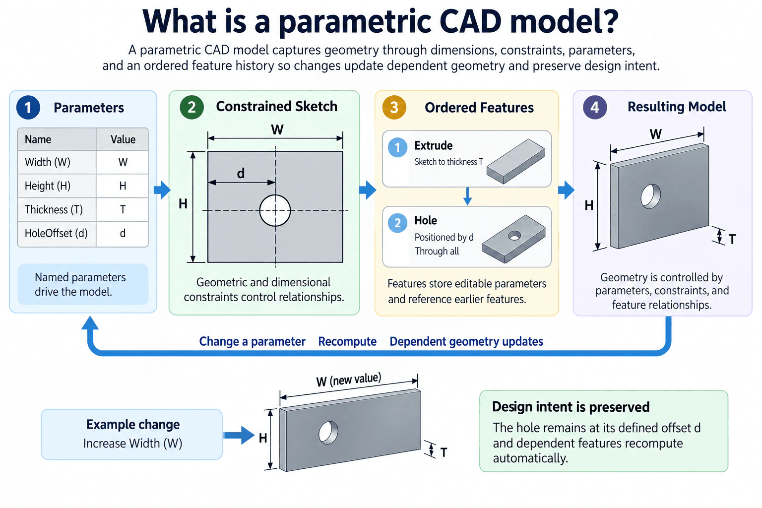
A parametric CAD model is a model whose geometry is controlled by defined parameters, dimensions, constraints, and relationships between features. For example, I might define a plate using width W, height H, thickness T, and a hole offset d. A constrained sketch defines the basic shape, an extrusion creates thickness T, and a later hole feature uses the defined offset d. If I change a driving value such as W, the CAD system recomputes dependent geometry according to those relationships. The goal is to capture design intent so expected changes produce predictable results.
Detailed Explanation
A parametric CAD model represents geometry through editable parameters and relationships rather than only fixed shapes. The important idea is design intent. Dimensions, sketch constraints, feature references, and feature order define how the model should behave when a driving value changes.
Useful Questions to Ask the Interviewer
Are you asking mainly about a single part model, or should I also discuss assembly relationships?
Would you like a simple example showing how one parameter change propagates through the feature tree?
Should I discuss model robustness and reference selection as part of the answer?
How to Explain It in an Interview
Engineering Method
I would begin with the purpose of the model and the changes it must accommodate. For a simple hypothetical mounting plate, I could define width W, height H, thickness T, and hole offset d as driving parameters.
I would create a constrained rectangular sketch using dimensions and geometric constraints. The sketch drives an extrusion to thickness T. A later hole feature is positioned using the defined offset d. This creates an ordered dependency in which the sketch drives the extrusion and the hole depends on the earlier geometry.
When a driving value such as W changes, the CAD system recomputes dependent geometry. The engineering objective is not merely that the model changes, but that it changes according to the intended relationships.
Design Reasoning
Good parametric modeling depends on deliberate references and feature order. I prefer stable references that express design intent, such as primary planes, sketch geometry, centerlines, or deliberately created reference geometry, instead of incidental edges that may disappear after an upstream change.
For the plate example, increasing W should widen the plate while the hole remains at its defined offset d. That behavior demonstrates that the constraint scheme captures the intended relationship.
Assumptions And Checks
I would test representative parameter changes and confirm that the model regenerates without broken sketches or failed features. I would check that constraints remain valid, dependent features still reference the intended geometry, configurations remain consistent when applicable, and downstream drawings still represent the model correctly.
For an assembly, I would additionally review assembly constraints, required clearance, and interference. Mass properties can also be checked when geometry changes affect engineering decisions.
A key limitation is that a model can be parametric without being robust. Poor references, unnecessary dependencies, or weak constraint logic can cause failures when dimensions change. A useful parametric model therefore combines editable parameters with a model structure that expresses the intended engineering relationships.
Why Interviewers Ask This
Interviewers want to know whether I understand that CAD geometry can be controlled by parameters, dimensions, constraints, references, and ordered features rather than treated as disconnected geometry. They are also evaluating whether I can capture design intent so an expected engineering change causes dependent geometry to update predictably.
Common interview mistakes
Common mistakes include leaving important sketches insufficiently constrained, referencing temporary edges or faces instead of stable geometry, creating unnecessary dependencies between unrelated features, using feature order that does not match design intent, and assuming that successful regeneration proves the model is correct. Another mistake is changing a parameter without checking dependent features, configurations, assembly clearance, mass properties, or downstream drawings when those checks are relevant.
Interview tip
Use one simple example and explain the dependency clearly. Define a few parameters such as W, H, T, and d, show how the sketch and features depend on them, then explain what should remain logically consistent when one parameter changes. This demonstrates design intent more effectively than only defining parametric modeling in abstract terms.
Interviewer may ask next
How would you check whether a parametric CAD model is robust?
I would change representative driving parameters through their expected ranges and regenerate the model. I would check for failed sketches, broken references, incorrect feature behavior, configuration inconsistencies, and unexpected geometry. When relevant, I would also check assembly constraints, clearance, interference, mass properties, and downstream drawing compatibility. The objective is to confirm that the model responds according to its intended relationships rather than merely rebuilding without an error message.
What changes if the hole should stay centered when the plate width changes instead of remaining at a fixed offset d?
I would change the design relationship rather than manually repositioning the hole. The hole center could be constrained to the plate centerline, or its position could be defined through a relationship derived from width W. Then a change to W would move the hole according to that rule. This illustrates why design intent matters because the parameterization should encode the required functional relationship, whether that is a fixed offset, a centered location, or another controlled dependency.
12. What does design intent mean in a parametric CAD model?Cad Modeling And Design IntentEasy
i Question Details
Explain how dimensions, constraints, datums, feature relationships and reference choices preserve function when requirements change.
Short Interview Answer (30-60 seconds)
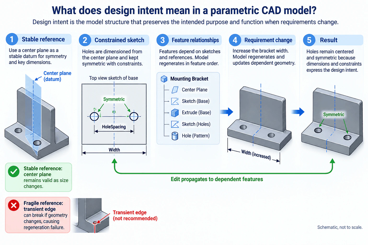
Design intent is the logic built into a parametric CAD model that defines how geometry should behave when requirements change. For example, if two mounting holes must stay symmetric as a bracket width changes, I would reference them from a stable center plane and constrain the sketch symmetrically instead of locating them from a transient edge. Dimensions control size, constraints preserve relationships, datums provide stable references, and the feature tree controls dependencies. Good design intent lets dependent features update predictably while preserving the required function.
Detailed Explanation
Design intent means structuring a parametric CAD model so the functional relationships that matter remain true when a driving requirement changes. The goal is not simply to create the correct geometry once. The model should also respond predictably to expected edits.
Useful Questions to Ask the Interviewer
Which geometric relationships must remain unchanged when dimensions change?
Which dimensions or configurations are expected to change most often?
Will the part depend on assembly interfaces or datums that must remain stable?
How to Explain It in an Interview
Engineering Method
I would first define the part purpose and the relationships that must survive change. For the bracket example, assume the two mounting holes must remain symmetric about the bracket center when the overall width changes.
I would use the center plane as a stable datum. The hole sketch would reference that plane, and symmetry plus appropriate dimensions would control the hole locations. This captures the functional rule directly in the model rather than relying on where geometry happens to be at one size.
The feature tree should also express clear dependencies. A base sketch can drive the base extrusion, followed by the hole sketch and hole feature. Dependent features should reference intentional sketches, datums, axes, or other stable geometry whenever possible.
Design Reasoning
Dimensions define size. Constraints define relationships such as symmetry. Datums provide persistent reference geometry. Feature relationships determine how upstream edits propagate through downstream features.
If the bracket width increases, the base updates and the dependent geometry regenerates. Because the holes are constrained from the center plane, they remain centered and symmetric. That behavior demonstrates the design intent.
A fragile alternative is referencing an important feature from a transient edge created by another feature. If an upstream change removes or alters that edge, the downstream reference can fail or attach incorrectly. A stable datum reduces that risk because its purpose is independent of a particular generated edge.
Assumptions And Checks
After changing a driving dimension, I would regenerate the model and inspect the feature tree for failures. I would confirm that the center plane remains valid, the hole symmetry is still satisfied, and the resulting geometry still meets the intended function.
For an assembly, I would also verify assembly constraints, clearance, and interference where applicable. For configuration based designs, I would check configuration consistency. I would review mass properties and downstream drawing compatibility when those outputs are affected by the geometry change.
The key idea is that good design intent makes expected changes predictable, traceable, and consistent with function.
Why Interviewers Ask This
Interviewers are evaluating whether you understand that a good parametric CAD model is more than the correct shape at one moment. They want to see whether you can use dimensions, constraints, datums, reference choices, and feature relationships so expected requirement changes preserve the intended function and regenerate predictably.
Common interview mistakes
Common mistakes include dimensioning related geometry independently instead of expressing the functional relationship, leaving important sketches under constrained, referencing transient edges instead of stable datums, creating unnecessary dependencies between features, and arranging the feature tree without considering how upstream changes affect downstream geometry. Another mistake is checking only whether the model regenerates instead of confirming that the regenerated model still preserves the intended function.
Interview tip
Use one simple change example. State what must remain functionally true, identify the stable datum and constraints that encode that rule, then explain what should happen when a driving dimension changes. For this bracket, increasing the width while the mounting holes remain symmetric about the center plane is a clear demonstration of design intent.
Interviewer may ask next
How would you validate that a model actually preserves its intended design relationships?
I would make representative changes to the driving dimensions and regenerate the model. I would inspect the feature tree for failures, confirm that important constraints such as symmetry remain satisfied, and verify that dependent features still reference the intended geometry. If the part belongs to an assembly, I would also verify assembly constraints, clearance, and interference where applicable. I would review configurations, mass properties, and affected drawings when those outputs depend on the modified geometry.
What would you do if the bracket width changed frequently but a mounting hole was located from an outer edge?
If the functional requirement is that the holes remain centered and symmetric, I would replace the transient edge reference with a stable center plane reference. I would constrain the hole sketch symmetrically about that plane and use the appropriate driving dimensions for spacing. Then a width change can propagate through the model while preserving the intended hole relationship.
13. How do you capture design intent before starting detailed CAD?Cad Modeling And Design IntentMedium
i Question Details
Identify primary datums, key interfaces, symmetry, controlled dimensions, likely variants and expected engineering changes before feature creation.
Short Interview Answer (30-60 seconds)
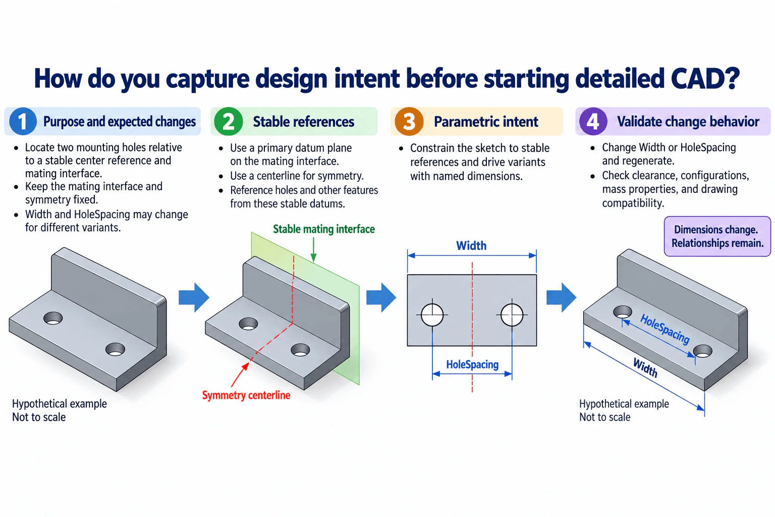
Before detailed CAD, I define what the part must do, which interfaces and relationships must remain stable, and which dimensions are expected to change. For a mounting bracket, I might keep the mating interface and symmetry reference fixed while allowing Width and HoleSpacing to vary. I then base sketches and constraints on stable datums or interfaces, use named driving dimensions for expected variants, and plan the feature order so those relationships survive regeneration. Finally, I vary the controlled dimensions and check clearance, configurations, mass properties, and drawing compatibility.
Detailed Explanation
I capture design intent by deciding what must remain invariant and what is allowed to change before I build the detailed feature tree. The model should express functional relationships rather than simply reproduce one geometry state.
Useful Questions to Ask the Interviewer
Which interfaces or mounting relationships must remain fixed when the design changes?
Which dimensions or configurations are expected to vary?
Are there assembly clearance, mass property, or drawing requirements that must remain consistent across variants?
How to Explain It in an Interview
I would start with the purpose of the part or assembly and identify the expected engineering changes. In the bracket example, I would treat the mating interface and symmetry relationship as stable while allowing Width and HoleSpacing to change for different variants.
Next, I would choose stable references. I prefer primary datum planes, the origin, a functional mating interface, or another reference that is unlikely to disappear as the model changes. I would avoid making important features depend on incidental edges when a more stable datum or interface can express the same intent.
Then I would create sketches that capture the intended relationships. The mounting holes can be located relative to the symmetry centerline and the stable mating interface. Width and HoleSpacing can be named driving dimensions so a new variant changes controlled parameters rather than requiring manual repositioning of geometry. Constraints should capture symmetry, alignment, and other relationships that must remain true.
I would also plan feature order before adding detail. Features that establish the main functional shape and stable references should appear before features that depend on them. That keeps the feature tree easier to understand and reduces fragile dependencies.
Finally, I would validate change behavior rather than checking only the original geometry. I would change Width or HoleSpacing and regenerate the model. I would confirm that the mating interface and symmetry relationship remain intact, then check assembly clearance or interference, configuration consistency, mass properties, and downstream drawing compatibility.
The key idea is that design intent is not just a set of dimensions. It is the combination of stable references, controlled parameters, constraints, and model structure that allows expected engineering changes while preserving functional relationships.
Why Interviewers Ask This
Interviewers want to see whether I can translate functional needs and expected engineering changes into a stable parametric model structure before creating detailed features. They are evaluating whether I can identify durable references, control important dimensions, represent symmetry and interfaces explicitly, anticipate variants, and validate that the model remains useful when requirements change.
Common interview mistakes
Common mistakes include constraining important features to incidental edges, adding dimensions without deciding which ones should drive variants, creating conflicting or redundant constraints, building fragile feature dependencies, and validating only the nominal model instead of testing expected parameter changes. Another mistake is treating geometric appearance as design intent without explicitly capturing the functional interface, symmetry, clearance, or assembly relationship behind it.
Interview tip
Use one simple part example and separate fixed relationships from expected changes. Explain why each reference is stable, which dimensions are controlled, how feature order supports those relationships, and how you would prove that the model still behaves correctly after a change. That demonstrates design intent judgment rather than merely listing CAD commands.
Interviewer may ask next
How would you validate that the captured design intent is robust?
I would exercise the expected changes deliberately. I would vary the named driving dimensions across representative configurations, regenerate the model, and confirm that the stable mating interface, symmetry, and dependent features remain correct. I would then check assembly clearance or interference, configuration consistency, mass properties, and drawing compatibility. Successful regeneration alone is not sufficient if a functional relationship changes unintentionally.
What would you change if the mating interface also became a variable design feature?
I would reconsider which reference should be the stable parent of the model. Instead of treating the mating interface as invariant, I might anchor the design to a primary datum system, origin, or another functional reference that remains common across variants. I would then parameterize the interface and review dependent sketches, assembly constraints, and features so the revised dependency structure matches the new engineering intent.
14. How do you prove that a parametric CAD model is robust?Cad Modeling And Design IntentMedium
i Question Details
Change key parameters across the expected range and verify successful rebuilds, stable references, valid geometry, mass properties and critical interfaces.
Short Interview Answer (30-60 seconds)
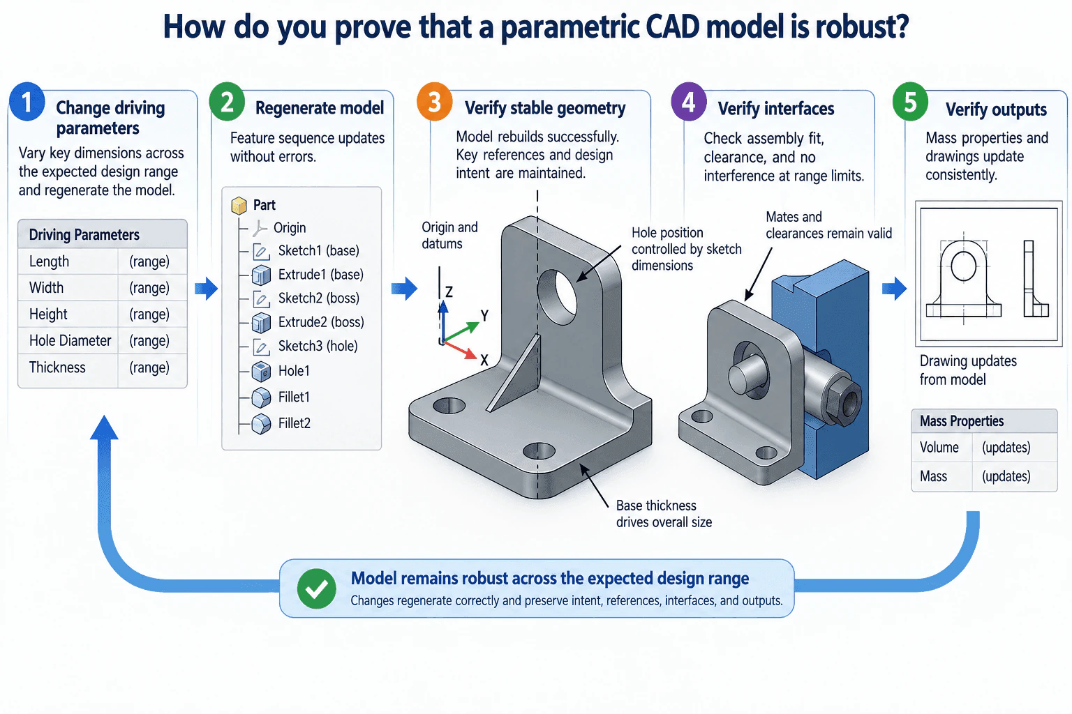
I prove robustness by changing the key driving parameters across the expected design range and regenerating the model after each change. I verify that the feature tree rebuilds successfully, stable references and intended geometry are preserved, assembly interfaces remain valid without unintended interference, and dependent outputs such as mass properties and drawings update consistently. A model is robust only within the ranges and configurations that were actually exercised and checked.
Detailed Explanation
A robust parametric CAD model should accommodate the design changes it was created to support while preserving the intended geometry, references, interfaces, and downstream outputs. For the bracket example, the driving parameters can include length, width, height, hole diameter, and thickness. Their actual allowable ranges must come from the design requirements rather than being invented during validation.
Useful Questions to Ask the Interviewer
Which dimensions or configurations are expected to change during normal design iteration?
Which assembly interfaces and clearances are critical at the parameter limits?
Should the robustness check include drawings and mass properties as downstream outputs?
How to Explain It in an Interview
Engineering Method
I start with the model purpose and the dimensions that represent real design decisions. I use stable references such as the origin, datum geometry, and properly constrained sketches, then order the feature tree so dependent features are built from intentional parent geometry.
Next, I change the important driving parameters across their expected ranges and regenerate the model after each change. I check that the feature sequence completes without errors, references remain valid, and the geometry still expresses the intended design. For example, a hole position should remain controlled by its sketch dimensions and intended reference geometry rather than drifting because of a fragile edge reference.
For an assembly, I then verify the critical interfaces. Mates or assembly constraints must remain valid, required clearances must still exist, and there should be no unintended interference at the tested range limits. A successful part regeneration does not by itself prove that the assembly remains usable.
Finally, I verify dependent outputs. Mass properties should recalculate from the changed geometry, and associated drawings should continue to update from the model consistently.
Assumptions And Checks
I document the parameter ranges and configurations that were exercised because robustness is demonstrated only within those tested conditions. I also check combinations of parameters when their interaction could create a failure that a single parameter test would miss.
Design Reasoning
The evidence follows one traceable path: change the driving parameters, regenerate the feature tree, confirm stable geometry and references, validate interfaces, and verify downstream outputs. If any step fails, I identify the dependency that caused the failure, revise the model structure or valid parameter range, and repeat the same validation sequence.
Why Interviewers Ask This
Interviewers want to know whether I can distinguish a model that only works at one nominal condition from a model that reliably preserves design intent as its driving parameters change. They are evaluating how I structure references, features, constraints, interfaces, and validation so the CAD model remains dependable through realistic design changes.
Common interview mistakes
Common mistakes include testing only the nominal configuration, treating successful regeneration as complete proof, using fragile references when stable datums or sketches are available, ignoring assembly interference at range limits, testing parameters only in isolation when combinations matter, and failing to verify drawings or mass properties after geometry changes.
Interview tip
Describe robustness as evidence from controlled parameter changes. State which parameters are varied, explain how stable references and feature order preserve design intent, name the checks performed after regeneration, and include assembly interfaces and downstream outputs. Do not claim robustness outside the parameter ranges and configurations that were actually tested.
Interviewer may ask next
What would you do if the model rebuilds successfully but an assembly interference appears at one parameter limit?
I would treat that configuration as a failed robustness case even though the part regenerated successfully. I would identify which driving dimension or interface relationship created the interference, confirm the required clearance, and decide whether the model structure should change or whether the allowable parameter range should be constrained. I would then repeat the regeneration and interface checks across the affected range.
How would your validation change if several related dimensions must change together?
I would define the intended relationships explicitly through dimensions, constraints, equations, or controlled configuration logic, then test representative combinations at the expected limits and important intermediate conditions. The goal is to preserve real design relationships without creating unnecessary dependencies that make the feature tree fragile.
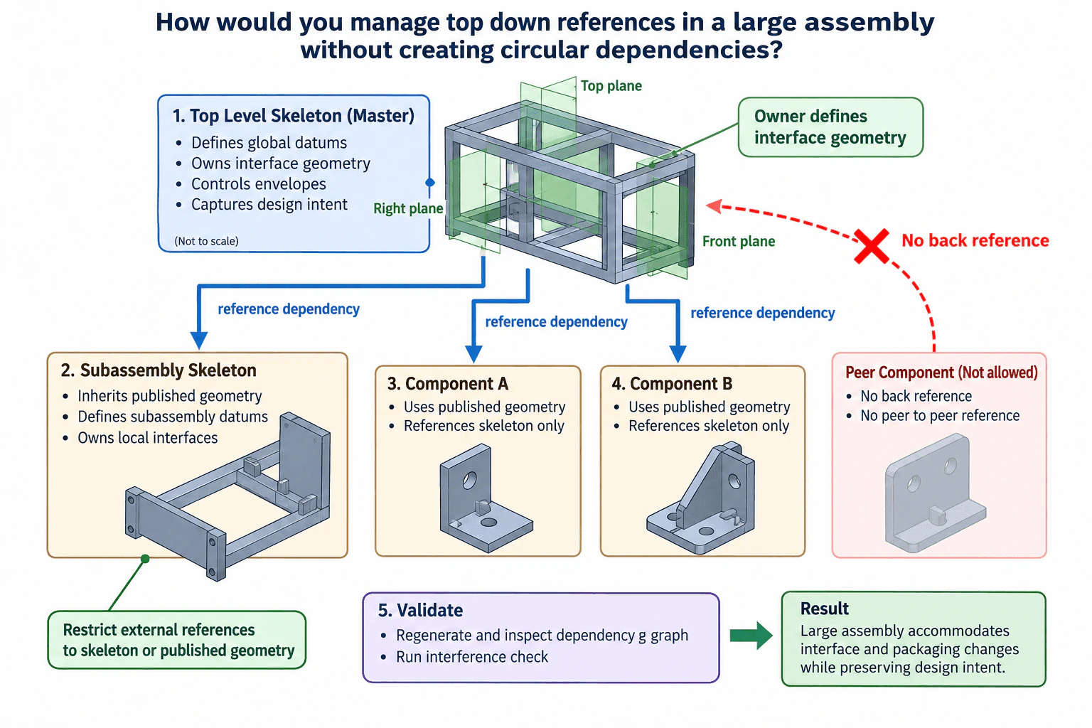
15. How would you manage top-down references in a large assembly without creating circular dependencies?Cad Modeling And Design IntentHard
i Question Details
Define controlled skeleton or master references, ownership of interface geometry, update direction and rules that prevent uncontrolled cross-part links.
Short Interview Answer (30-60 seconds)
I would create a controlled top level skeleton or master model that owns global datums, packaging envelopes, and shared interface geometry. Subassembly skeletons and components may reference only approved geometry above them in the hierarchy. Components should not reference their parent skeleton backward or depend directly on peer components, so the dependency direction remains master to subassembly skeleton to component. After a change, I would regenerate the assembly, inspect the dependency graph, and run interference and configuration checks before accepting the update.
Detailed Explanation
The assembly purpose is to coordinate many components while allowing interface and packaging changes without losing design intent. I would make the top level skeleton the authoritative owner of shared global datums, packaging envelopes, and interface geometry. A subassembly skeleton may inherit published geometry from the master, define local datums, and own interfaces that belong only to that subassembly. Individual components then consume the appropriate skeleton geometry rather than referencing neighboring components directly.
Useful Questions to Ask the Interviewer
Does the CAD system provide skeleton models, published geometry, or another controlled external reference mechanism?
Which interface dimensions or packaging envelopes are expected to change frequently?
Are there existing rules for allowable external references and dependency reviews?
How to Explain It in an Interview
I would define the dependency hierarchy before detailed component modeling. The top level skeleton owns shared datums, packaging envelopes, and interface geometry. This creates one clear owner for information that multiple parts must follow.
If a subassembly needs its own coordination layer, I would create a subassembly skeleton that inherits only approved published geometry from the master. It can define subassembly datums and own local interfaces. Components then reference their controlling skeleton or published geometry rather than neighboring components.
The update direction stays one way: master to subassembly skeleton to component. I would not allow a component to drive geometry back into its parent skeleton, and I would not allow peer to peer external references. That prevents loops such as Component A depending on Component B while Component B also depends on Component A.
For stable references, I would prefer intentional datums, sketches, planes, axes, and published interface geometry over incidental model edges or faces that may disappear when the feature tree changes. Component specific detail remains controlled by local dimensions and constraints unless it is truly shared design intent.
When an interface or packaging envelope changes, I would regenerate from the top of the hierarchy and inspect the dependency graph for unexpected links. I would then check assembly constraints, configuration consistency, clearance and interference, mass properties where relevant, and downstream drawing compatibility.
The main tradeoff is control versus coupling. A strong skeleton structure makes ownership and updates easier to trace, but putting too much component detail into the master can make the whole assembly unnecessarily dependent on it. I would therefore keep only shared design intent in the master and keep component specific features inside each component.
Why Interviewers Ask This
Interviewers want to see whether I can use top down parametric modeling at assembly scale without creating a fragile feature tree. The key judgment is whether I can define clear geometry ownership, stable references, one way update direction, and validation rules that keep interfaces coordinated while preventing circular or uncontrolled cross part dependencies.
Common interview mistakes
Common mistakes include allowing components to reference neighboring components freely, creating references back into a parent skeleton, using unstable model edges instead of intentional datums or published geometry, duplicating ownership of the same interface, and accepting a successful regeneration without checking the dependency graph, configurations, clearance, interference, or downstream drawings.
Interview tip
State the dependency direction explicitly. Explaining that shared geometry has one owner and that references flow only from master to subassembly skeleton to component demonstrates stronger design intent than simply saying that you would use a skeleton model.
Interviewer may ask next
How would you validate that the reference structure is still healthy after a major assembly change?
I would regenerate from the top level, inspect the reference or dependency graph, and look for newly created external links that violate the allowed hierarchy. I would then verify assembly constraints, configuration consistency, clearance and interference, mass properties where relevant, and downstream drawing compatibility. A successful regeneration alone is not enough because the model can regenerate while still containing an unintended dependency.
What would you change if two components genuinely need closely coupled geometry?
I would move the shared relationship to the nearest common owner rather than letting the components reference each other. That owner may be the top level skeleton or a subassembly skeleton. Both components would then consume the same controlled interface geometry, which keeps the coupling explicit while preserving one way dependency flow and avoiding a peer to peer circular reference.
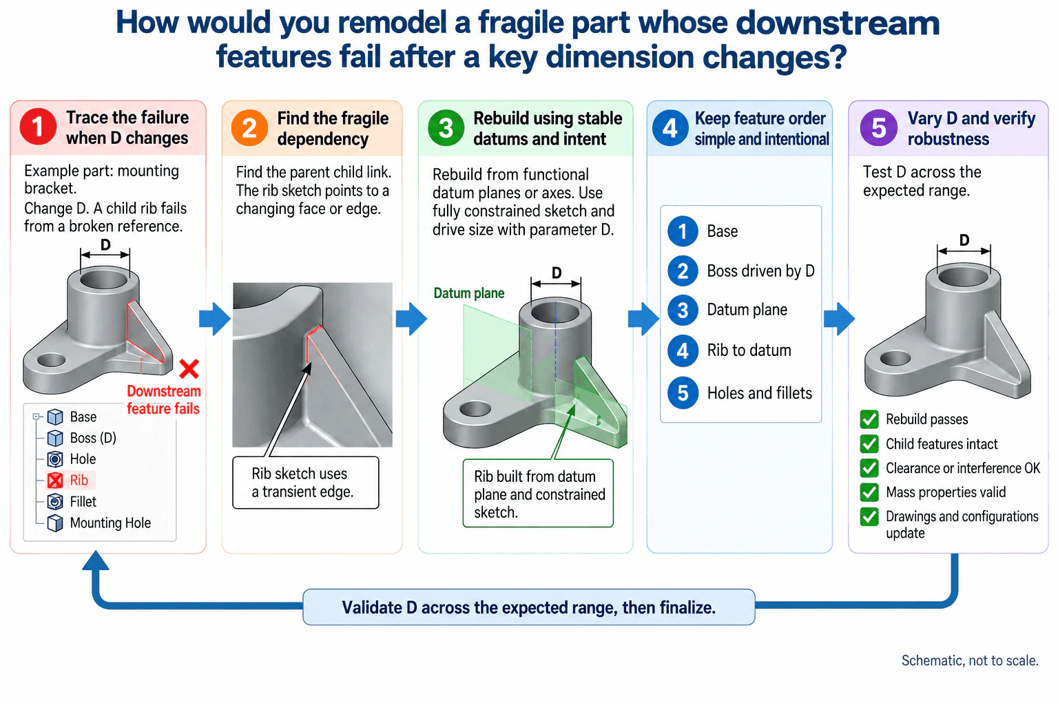
16. How would you remodel a fragile part whose downstream features fail after a key dimension changes?Cad Modeling And Design IntentHard
i Question Details
Trace failed references, identify unstable parent-child dependencies, rebuild around functional datums and simpler feature relationships, then regression-test the expected parameter range.
Short Interview Answer (30-60 seconds)
I would first reproduce the failure by changing the key dimension and rebuilding the model. Then I would trace the first failed child feature back to its parent references. If the rib sketch depends on a face or edge whose topology changes with dimension D, I would rebuild it from functional datum planes or axes and fully constrain the sketch around the intended geometry. I would keep D as the driving parameter, simplify the feature order, and regression test the expected range of D. I would verify rebuild success, downstream features, assembly clearance or interference, mass properties, configurations, and drawing updates before accepting the remodel.
Detailed Explanation
The problem is not just the broken rib. It is a fragile dependency structure. In the example, the part is a mounting bracket. Dimension D drives the cylindrical boss, and the downstream rib fails because its sketch references geometry that changes when D changes. The remodel should let D vary without breaking the intended downstream relationships.
Useful Questions to Ask the Interviewer
What range must dimension D support?
Which downstream features and assembly interfaces must remain functionally unchanged?
Which configurations and drawings must remain compatible?
How to Explain It in an Interview
Engineering Method
First, I would reproduce the failure by changing D and rebuilding the model. I would inspect the feature tree and parent child relationships to find the first failed reference rather than repairing later symptoms.
For this bracket, I would confirm whether the rib sketch references a changing face or edge. If it does, I would replace that transient reference with functional reference geometry, such as a datum plane or axis that represents the intended relationship.
I would then rebuild the rib from that datum and fully constrain its sketch. Dimension D would remain the driving parameter for the boss. The feature sequence would stay simple and intentional: base, boss driven by D, datum plane, rib to datum, then holes and fillets.
Assumptions And Checks
The allowable range of D is not supplied, so I would not invent one. I would test the range defined by the design requirements.
At each relevant value of D, I would rebuild the part and check that child features remain intact. If the part is used in an assembly, I would check clearance or interference with mating components. I would also review mass properties where they matter, confirm configuration consistency, and verify that downstream drawings update correctly.
Design Reasoning
The main design decision is to reference geometry that represents function instead of incidental topology. A face or edge created by an earlier feature may disappear or change identity when upstream geometry changes. Functional datums and constrained sketches make the intended dependency explicit.
I would consider the remodel complete only when the model rebuilds successfully across the required range of D and the dependent features, assembly relationships, configurations, mass properties, and drawings remain consistent.
Why Interviewers Ask This
Interviewers want to see whether I can diagnose fragile parametric dependencies, identify the first unstable parent child relationship, preserve design intent with stable references, simplify the feature tree, and validate that the remodeled part remains consistent across the required design range.
Common interview mistakes
Common mistakes include repairing only the final failed feature, keeping references to changing faces or edges, adding unnecessary constraints, creating obscure dependency chains, changing feature order without understanding parent child relationships, and testing only the nominal value of the driving dimension.
Interview tip
Explain the failure chain first, then explain the remodeled dependency structure. Show that you can distinguish the functional relationship from the particular face or edge used in the original model, and finish by describing how you would validate the expected range of the driving parameter.
Interviewer may ask next
How would you validate the remodeled model before release?
I would vary dimension D across its required range and rebuild at each relevant condition. I would verify that downstream features remain intact, assembly clearance or interference remains acceptable, configurations stay consistent, mass properties remain appropriate for the resulting geometry, and associated drawings update correctly. I would also inspect the feature tree for rebuild warnings or unexpected dependencies.
What would you do if the rib truly needs to move as dimension D changes?
I would keep that relationship intentional rather than referencing an incidental edge. I would drive the rib from suitable datum geometry, sketch constraints, equations, or another controlled reference so its motion follows D by design. The exact method depends on the geometry, but the dependency should remain explicit, understandable, and stable throughout the required parameter range.
17. What is a datum in GD&T?Gd&t And Tolerance AnalysisEasy
i Question Details
Define the theoretically exact reference established from a datum feature and explain its role in locating and orienting controlled features.
Short Interview Answer (30-60 seconds)
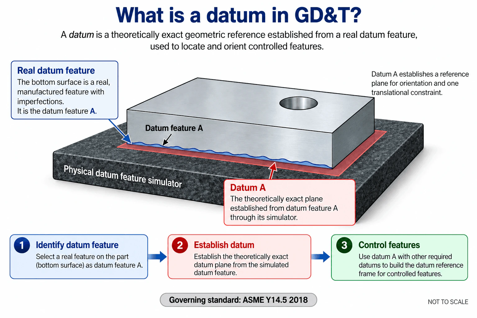
A datum in GD&T is a theoretically exact geometric reference, such as a plane, axis, line, or point, established from a real datum feature. In the planar example shown, the imperfect bottom surface is datum feature A. A physical datum feature simulator represents the mating or inspection interface and establishes the reference used to derive datum plane A. That exact plane provides orientation and one translational constraint and can combine with additional datums to form the datum reference frame used to locate and orient controlled features.
Detailed Explanation
A datum is an ideal geometric reference, not the manufactured feature itself. The manufactured surface, hole, width feature, or other specified feature is the datum feature. Because an actual feature contains manufacturing variation, GD&T uses theoretically exact geometry established from that feature as the reference for related controls.
In the illustrated planar example, the bottom surface is datum feature A. The part contacts a physical datum feature simulator representing the functional or inspection interface. From this setup, datum plane A is established as the theoretically exact reference. For a primary planar datum, this reference constrains translation normal to the plane and rotation about two axes lying in the plane. That is why the diagram summarizes its role as providing orientation and one translational constraint.
The governing convention shown is ASME Y14.5 2018. If an ISO GPS drawing governed instead, I would use the terminology and rules of that system rather than mix conventions.
Useful Questions to Ask the Interviewer
Are we using ASME Y14.5 2018 or an ISO GPS standard for the drawing?
Is datum feature A intended to represent the primary functional mounting interface?
Are you asking about a single planar datum or about a complete datum reference frame with additional datums?
How to Explain It in an Interview
Engineering Method
I would first separate the actual feature from the ideal reference. Datum feature A is the real manufactured surface and can contain form variation. The datum is theoretically exact geometry established from that feature using the applicable datum simulation method.
For the planar example, the physical datum feature simulator represents the contacting inspection or mating interface. The resulting datum plane provides the first reference for orienting and constraining the part. A primary planar datum normally constrains three degrees of freedom: one translation normal to the plane and two rotations.
Assumptions And Checks
I would confirm the governing standard and edition first. Here the diagram uses ASME Y14.5 2018. I would also confirm that the selected datum feature represents the functional assembly constraint and that the inspection setup simulates that interface appropriately.
A single planar datum does not fully locate a part in three dimensional space. Additional datum features are added when the function requires the remaining degrees of freedom to be constrained.
Design Reasoning
The datum gives geometric controls a repeatable reference. If a controlled feature must be oriented or located relative to a mounting face, the datum reference tells design, manufacturing, and inspection how that relationship is established.
The key distinction is: real datum feature, datum simulation, theoretically exact datum, then controlled features referenced through the datum reference frame.
Why Interviewers Ask This
Interviewers want to confirm that you understand the difference between a real datum feature and the theoretically exact datum established from it. They are also testing whether you can connect that reference to functional orientation, location, inspection, and a datum reference frame without confusing physical part geometry with ideal reference geometry.
Common interview mistakes
Common mistakes include calling the physical surface itself the datum, selecting datum features only because they are convenient to measure, assuming one planar datum fully constrains a part, confusing size tolerances with geometric controls, treating the physical simulator as the theoretically exact datum itself, and mixing ASME Y14.5 and ISO GPS conventions without stating which system governs.
Interview tip
State the distinction clearly: the datum feature is real and imperfect, while the datum is theoretically exact. Then explain that the datum is established from the datum feature through the applicable simulation and contributes to the datum reference frame used to orient or locate controlled features.
Interviewer may ask next
How would you validate that a planar datum is being established correctly during inspection?
I would confirm the governing drawing standard, identify the specified datum feature, and verify that the inspection setup uses an appropriate datum feature simulator representing the intended functional interface. I would check that the part contacts the simulator consistently and that the resulting reference is used correctly when evaluating the controlled feature. I would also review whether surface condition, accessibility, or the measurement method could cause the inspection setup to differ from the intended functional constraint.
What changes if datum A alone does not fully constrain the part?
Additional datum features are referenced according to the functional assembly constraints. A primary planar datum typically constrains three degrees of freedom. A properly selected secondary datum can constrain two more, and a tertiary datum can constrain the remaining degree of freedom when a complete six degree of freedom datum reference frame is required. The exact constraint pattern depends on the types and sequence of the referenced datum features.
18. What do DFM and DFA mean in mechanical product development?Manufacturing Processes And DfmEasy
i Question Details
Distinguish designing parts for capable, economical manufacturing from designing assemblies for simple, reliable assembly.
Short Interview Answer (30-60 seconds)
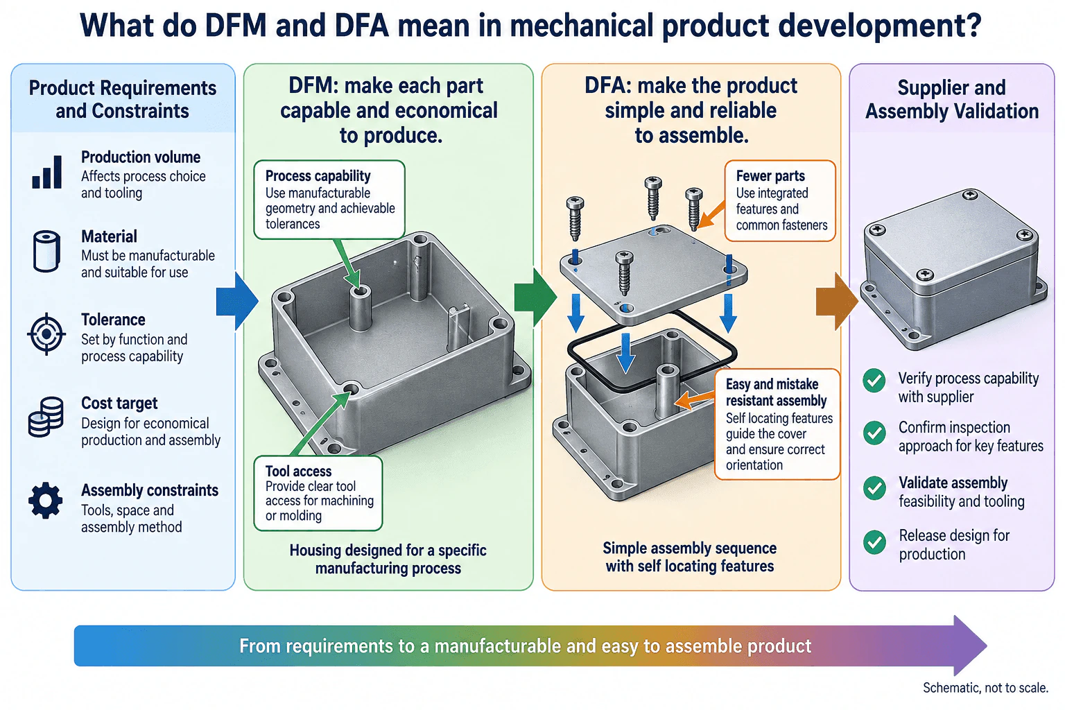
DFM means Design for Manufacturing. It focuses on making each part capable and economical to produce with the intended manufacturing process. That means considering production volume, material, tolerances, cost, process capability, manufacturable geometry, inspection, and process specific access requirements. DFA means Design for Assembly. It focuses on making the product simple and reliable to assemble by reducing unnecessary parts, using common fasteners where appropriate, adding self locating or mistake resistant features, and creating a clear assembly sequence. DFM and DFA work together so the individual parts are practical to make and the complete product is practical to assemble.
Detailed Explanation
DFM and DFA address two related but different design questions. DFM asks whether each part can be produced repeatedly and economically with the intended process. DFA asks whether those parts can be assembled into the finished product simply, reliably, and with low risk of mistakes.
Useful Questions to Ask the Interviewer
What production volume and manufacturing processes are being considered?
Which tolerances, interfaces, or assembly requirements are function critical?
Are there known supplier, inspection, tooling, or assembly constraints?
How to Explain It in an Interview
Engineering Method
I would first define production volume, material, functional tolerances, cost target, and assembly constraints. Those inputs guide the manufacturing process and determine what geometry is practical.
For DFM, I would choose a suitable process such as machining, sheet metal, casting, molding, forging, welding, or additive manufacturing from the part requirements. Then I would review the geometry against that process. For the housing example, I would confirm that important features have achievable tolerances and that cutting tools can reach features that require machining. If molding or casting were selected, I would instead review process specific constraints such as draft, wall thickness, mold or die access, and release geometry.
For DFA, I would examine how the housing, seal, cover, and fasteners come together. I would minimize unnecessary parts, use common fasteners where appropriate, provide self locating features, and create a simple assembly sequence. If the cover could be installed incorrectly, I would use mistake resistant geometry that prevents or strongly constrains the wrong orientation.
Assumptions And Checks
I would not assume that every drawing tolerance is economical or repeatable. I would review critical dimensions with the supplier, compare them with demonstrated process capability, and define an inspection approach for key features. I would also confirm assembly tooling access and verify that the planned assembly sequence is physically feasible.
Design Reasoning
The key distinction is that DFM improves how individual parts are manufactured, while DFA improves how the product is assembled. A design can be easy to manufacture but difficult to assemble, or easy to assemble but expensive to manufacture. The final design should balance capable manufacturing, reliable assembly, supplier capability, inspection needs, tooling, and total cost before production release.
Why Interviewers Ask This
Interviewers want to see whether the candidate can distinguish part manufacturability from assembly simplicity, connect design decisions to process capability and supplier capability, and consider production cost, inspection, assembly reliability, and tooling before releasing a design.
Common interview mistakes
Common mistakes include treating DFM and DFA as the same activity, choosing a process without considering production volume, specifying unnecessarily tight tolerances, ignoring machining tool access or process specific geometry constraints, assuming a supplier can meet every drawing requirement without capability evidence, using unnecessary parts or excessive fastener variety, and allowing an assembly sequence that permits incorrect orientation.
Interview tip
State the distinction first: DFM is about making each part practical and economical to manufacture, while DFA is about making the finished product simple and reliable to assemble. Then use one connected example, such as a housing whose geometry must suit the manufacturing process while its cover, seal, locating features, and fasteners must support a clear and mistake resistant assembly sequence.
Interviewer may ask next
How would you validate that a DFM decision is actually manufacturable?
I would review the critical geometry and tolerances with the intended supplier or manufacturing team, compare them with demonstrated process capability, confirm the relevant process constraints and required access, and define an inspection method for key features. If capability evidence shows that a requirement is difficult or costly to hold, I would revisit the tolerance, geometry, process, or functional requirement rather than assuming that the drawing alone makes the design manufacturable.
How would your DFM and DFA approach change if production volume increased significantly?
Higher production volume can justify different processes and tooling because recurring part and assembly cost becomes more important relative to initial tooling cost. I would reconsider process selection, simplify repeatable geometry, review process specific constraints, and look more closely at reducing assembly steps, part count, fastener variety, handling, and opportunities for incorrect orientation. The preferred design could therefore change even if the product function remains the same.
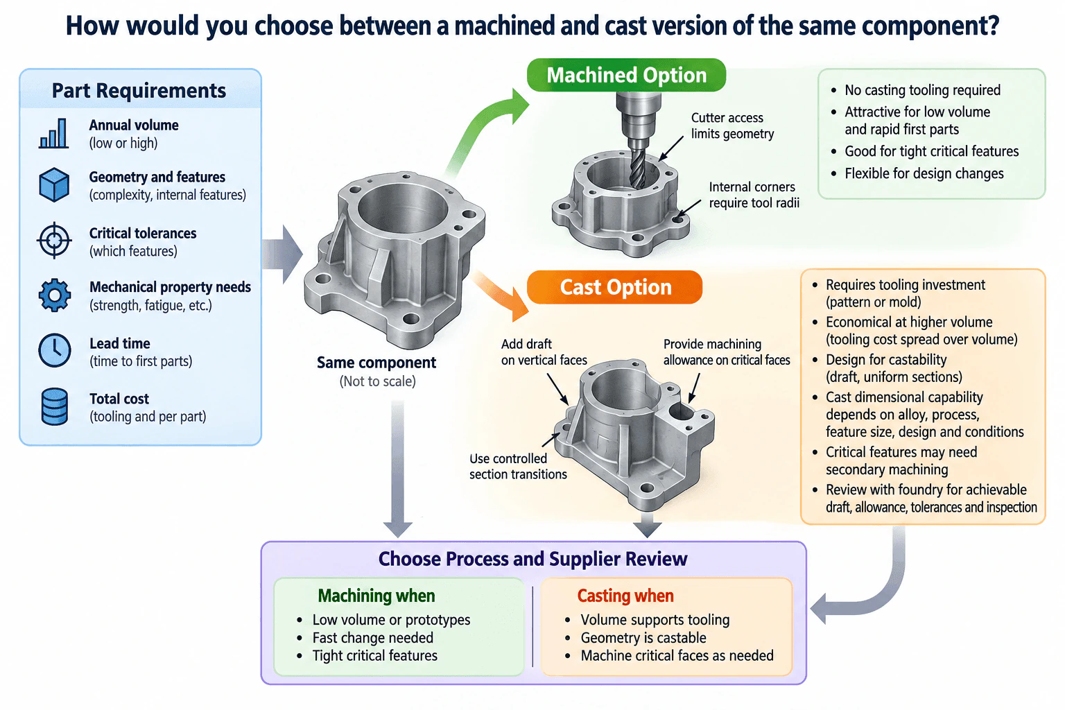
19. How would you choose between a machined and cast version of the same component?Manufacturing Processes And DfmMedium
i Question Details
Compare annual volume, geometry, draft and section rules, tooling cost, machining allowance, tolerance capability, mechanical properties and lead time.
Short Interview Answer (30-60 seconds)
I would compare annual volume, geometry, critical tolerances, material and mechanical property requirements, lead time, and total cost. Machining is often attractive for lower volumes, rapid first parts, likely design changes, or features that need tight control without casting tooling. Casting becomes more attractive when the volume can justify tooling and the geometry can follow casting rules such as draft and controlled section transitions. I would add machining allowance only on critical cast surfaces that need finishing, then confirm process capability, inspection requirements, supplier capability, and total delivered cost before choosing.
Detailed Explanation
I would treat machining and casting as two complete manufacturing routes for the same functional component. The decision is not based on piece cost alone. I would compare the geometry each process can produce, the expected annual volume, required tolerances, material and mechanical property requirements, lead time, tooling cost, recurring cost, and supplier capability.
Useful Questions to Ask the Interviewer
What is the expected annual volume, and how stable is that forecast?
Which dimensions, surfaces, and mechanical requirements are critical to function?
Is the main priority fastest first parts, lowest recurring cost, or lowest total program cost?
How to Explain It in an Interview
I would first define the same requirements for both options: annual volume, material, geometry, critical tolerances, mechanical property needs, lead time, total cost, assembly constraints, and expected design changes.
For machining, I would check stock availability, cutter access, setup count, material removal, internal corner radii, inspection access, and cycle time. Machining does not require casting tooling and is flexible when the design may change, so it is often practical for prototypes and lower volumes. It can also produce tightly controlled critical features when the selected machine, tooling, setup, and supplier process are capable.
For casting, I would check whether the geometry is suitable for the selected casting process. I would review draft on withdrawal surfaces, controlled section thickness and transitions, tooling access, and areas where casting variation or distortion could affect function. Critical faces, bores, or interfaces may receive machining allowance so they can be finished after casting. I would not assume that every cast feature requires secondary machining.
The cost comparison should separate tooling investment from recurring part cost. Casting normally requires dedicated tooling, but that tooling cost can be distributed across larger production quantities. Machining generally needs less dedicated tooling investment, but machine time and material removal can increase recurring cost. I would compare total expected program cost rather than use an arbitrary volume threshold.
Tolerance capability must be evaluated by feature. I would identify which dimensions can remain as cast and which require machining, then review those requirements with the supplier using demonstrated process capability and an inspection plan.
For mechanical properties, I would confirm that the selected material form, casting process, machining stock, heat treatment when applicable, and acceptance requirements support the actual design needs. I would not assume a cast and machined route are mechanically equivalent simply because the nominal alloy name is similar.
Finally, I would compare lead time. Machining can often provide earlier first parts because dedicated casting tooling is not required. Casting may require additional time for tooling, process development, secondary machining, inspection, and supplier review.
I would select the route that meets functional requirements with acceptable manufacturing risk and the best total cost for the expected production plan, then validate the decision through supplier review, first article inspection, and capability evidence on critical features.
Why Interviewers Ask This
This tests whether I can select a manufacturing route from actual part requirements instead of choosing a process by habit. The interviewer is evaluating judgment around annual volume, geometry, tolerance capability, tooling investment, machining allowance, material and mechanical property requirements, lead time, supplier capability, inspection, and total cost.
Common interview mistakes
Common mistakes include choosing from piece cost alone, assuming annual volume automatically determines the process, ignoring casting tooling and development lead time, specifying unnecessarily tight tolerances on every surface, forgetting machining allowance on critical cast features, using cast geometry without adequate draft or controlled section transitions, ignoring cutter access and internal radii for machining, assuming nominally similar material routes have identical mechanical behavior, and accepting supplier capability without an inspection and process capability review.
Interview tip
Structure the answer around requirements, manufacturability, economics, process capability, and validation. Make it clear that annual volume changes the economics but does not decide the process by itself. Mentioning cutter access for machining, draft and controlled sections for casting, selective machining allowance, tooling cost, lead time, supplier review, and feature specific process capability demonstrates practical DFM judgment.
Interviewer may ask next
How would you validate that the selected casting process can hold the required critical dimensions?
I would classify the critical dimensions by whether they remain as cast or receive secondary machining. For as cast features, I would review the supplier process, tooling concept, inspection method, expected variation, and available process capability evidence. For machined critical features, I would define appropriate machining allowance and inspect the finished dimensions. Early production should include first article inspection and measurement of the critical characteristics before relying on routine production controls.
What would change if annual volume increased substantially after the first year?
I would repeat the total cost comparison using the new volume forecast. Higher volume allows casting tooling cost to be distributed across more parts, so the cast route may become more economical if the geometry is castable and the required quality can be maintained. I would still include tooling lead time, secondary machining, inspection, material requirements, supplier capacity, and any redesign needed to convert the existing machined geometry into a robust casting.
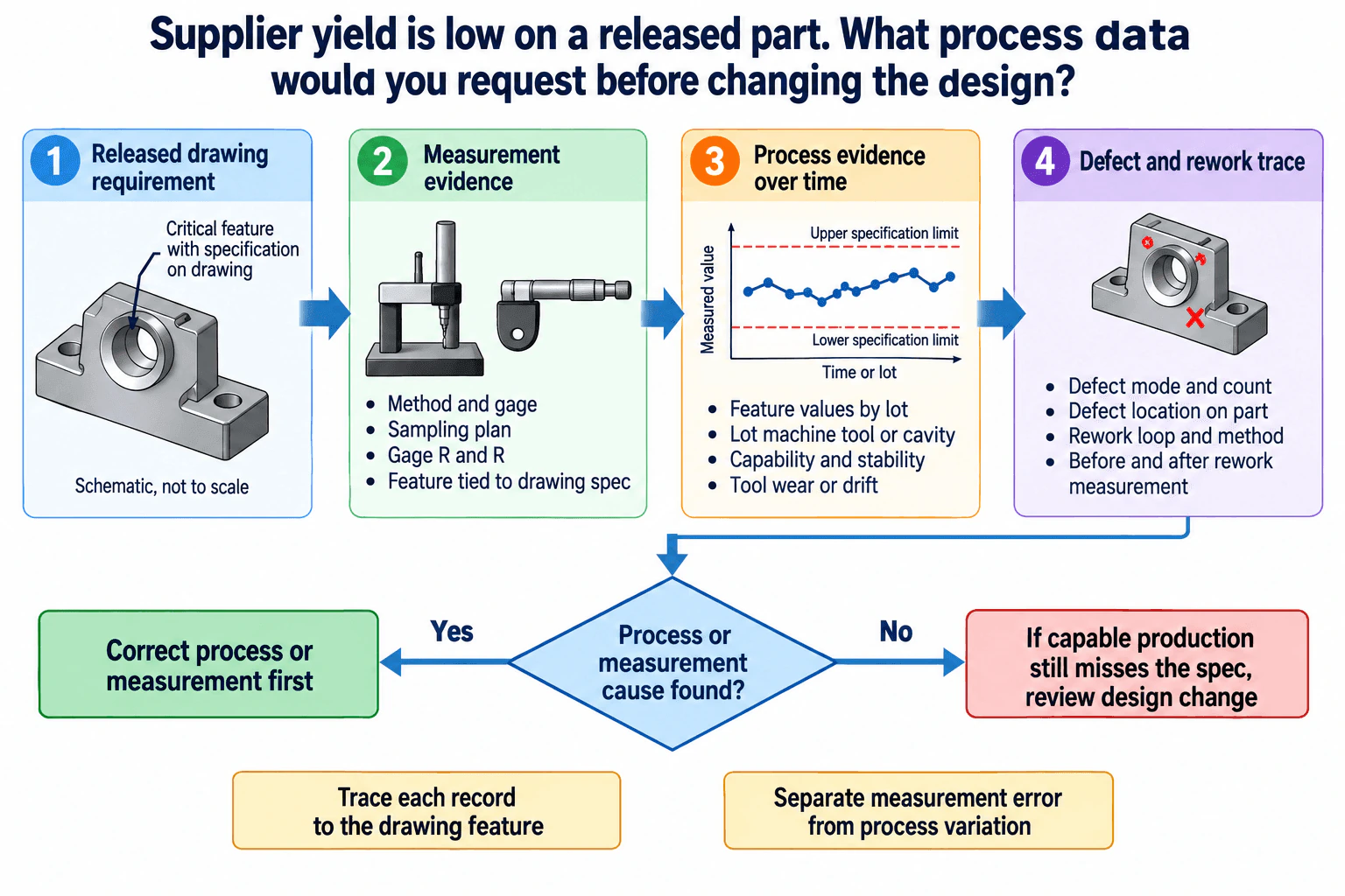
20. Supplier yield is low on a released part. What process data would you request before changing the design?Manufacturing Processes And DfmHard
i Question Details
Request defect modes, measurement method, capability trends, tool wear or drift, rework loops and feature-level data tied to the drawing requirement.
Short Interview Answer (30-60 seconds)
Before changing the design, I would request data tied directly to the failing drawing feature. I would ask for the measurement method and gage, sampling plan, gage R and R evidence, feature measurements by lot, machine, tool, or cavity, capability and stability trends, tool wear or drift history, defect modes and locations, and rework records with measurements before and after rework. I would first determine whether the yield loss comes from the measurement system or manufacturing process. If capable controlled production still cannot meet the drawing requirement, then I would review whether a design change is appropriate.
Detailed Explanation
The goal is to determine whether low yield is being caused by the drawing requirement, the measurement system, or the manufacturing process. I would not change a released design until the supplier data identifies which of those is actually limiting yield.
Useful Questions to Ask the Interviewer
Which drawing characteristic is driving the yield loss, and what specification applies to it?
Does the failure pattern change by lot, machine, tool, cavity, or another meaningful process source?
Has the supplier already evaluated the measurement system and process stability for that characteristic?
How to Explain It in an Interview
Engineering Method
I would start with the released drawing and identify the exact feature associated with scrap or rework. Every measurement, defect record, and process record should be traceable to that drawing feature.
Next, I would verify the measurement evidence. I would request the measurement method, gage or inspection equipment, sampling plan, and gage R and R or equivalent repeatability and reproducibility evidence. This helps separate measurement error from true process variation.
Then I would request feature values over time, not only the final yield percentage. I would want those values grouped by lot and, where applicable, by machine, tool, cavity, fixture, shift, or another meaningful process source. I would review process stability first, then capability relative to the drawing specification. Capability results are most useful when they describe a reasonably stable process.
I would also request tool wear, offset, maintenance, or drift history when those factors can influence the feature. A gradual dimensional shift can indicate process deterioration rather than an inherently unmanufacturable design.
Finally, I would review defect mode and count, defect location on the part, rework loop and method, scrap disposition where relevant, and measurements before and after rework. Rework can hide the original process problem if only final accepted measurements are reviewed.
Assumptions And Checks
I would confirm that the supplier is evaluating the correct released drawing feature and using consistent measurement definitions. I would also confirm that the data covers enough representative production to distinguish a persistent pattern from isolated events. I would not assume a universal capability acceptance value because the required criterion depends on the product, customer requirements, and quality plan.
Design Reasoning
If the evidence identifies a measurement or process cause, I would correct that cause first and verify the resulting yield. If the measurement system is trustworthy, the process is stable, and controlled production still cannot meet the specification at acceptable yield or cost, I would review a design change. Any proposed tolerance or geometry change would still need to preserve function, assembly, inspection, supplier capability, and cost requirements.
Why Interviewers Ask This
This tests whether the engineer can distinguish a design limitation from measurement error and manufacturing process variation before changing a released part. The interviewer is looking for disciplined supplier review, traceable evidence, correct interpretation of process capability, and sound judgment about when a design change is justified.
Common interview mistakes
Common mistakes are changing the tolerance before identifying the failing feature, relying only on overall yield instead of feature measurements, assuming the inspection system is correct without checking measurement variation, interpreting capability from an unstable process, ignoring tool wear or cavity specific behavior, overlooking rework loops, and accepting supplier conclusions that are not traceable to the drawing requirement.
Interview tip
Structure the answer around evidence before redesign. Start with the drawing feature, verify the measurement system, review feature data and process stability, trace defects and rework, and then explain the decision point for a design change. This shows that you protect product function while evaluating supplier capability and manufacturing variation systematically.
Interviewer may ask next
What would you do if the supplier reports poor capability but the measurement system has not been evaluated?
I would treat the capability result as provisional. I would first evaluate the measurement method, gage resolution, repeatability, reproducibility, and other relevant sources of measurement variation. If the measurement system contributes meaningful variation, I would correct or characterize it and then collect representative process data again before deciding whether the process or drawing requirement is responsible.
What if the supplier proves the process is stable but the required feature still causes excessive scrap?
I would review capability against the released specification and confirm that the supplier is using an appropriate process, tooling strategy, inspection method, and controlled operating condition. If stable controlled production still cannot meet the requirement at acceptable yield or cost, I would evaluate a design change with the engineering team. Any proposed tolerance or geometry change would still need to preserve function, assembly, inspection, and downstream requirements.
More questions load as you scroll
Disclaimer: This interview guide is for educational and informational purposes only. It is designed to help readers prepare, but it does not guarantee any interview result, hiring decision, offer, or outcome. Interview questions, hiring criteria, and preferred answers can vary by employer, interviewer, industry, location, and time. All answers, examples, and explanations in this guide are suggested examples for interview preparation, not definitive answers or instructions for professional practice. They are based on research and judgment, are provided without warranties of any kind, and should be adapted to the question, role, and applicable laws and professional requirements. Diagrams are simplified illustrations intended to highlight the main concepts and their relationships; actual situations, systems, and practices may be more complex. Alternative approaches may be equally valid or better suited to a particular question, context, or interviewer. To the fullest extent permitted by applicable law, the contributors and publisher are not liable for decisions made, actions taken, or losses incurred based on this guide.
State Laws and Professional Responsibilities: Laws and requirements governing an occupation vary by state and jurisdiction. You are responsible for checking the current laws, licensing requirements, and scope-of-practice rules that apply to your location and role, and for ensuring that your answers and actions comply with them. Adapt examples in this guide to those requirements. This guide is not legal advice.
Content Accuracy and Verification: To the fullest extent permitted by applicable law, we do not represent or warrant that interview guides, questions, answers, examples, or diagrams are accurate, complete, current, error-free, or suitable for any particular purpose. You are responsible for independently reviewing and verifying the information before relying on it.