
1. Sketch a refrigeration cycle on temperature-entropy axes and explain the processes.
I would draw temperature T vertically and specific entropy s horizontally, then add the saturation dome and four states. State 1 is saturated vapor leaving the evaporator. From 1 to 2, the compressor raises pressure and temperature through an idealized isentropic process, so entropy stays constant. From 2 to 3, the refrigerant rejects heat at high pressure, first desuperheating and then condensing to saturated liquid. From 3 to 4, the expansion valve throttles the refrigerant with h3 = h4, creating a colder liquid vapor mixture. From 4 to 1, the evaporator absorbs heat at low pressure until the refrigerant becomes saturated vapor again. For a steady cycle with negligible kinetic and potential energy changes, qout = qin + win per unit mass.
A standard idealized vapor compression refrigeration cycle can be analyzed as four steady flow control volumes: compressor, condenser, expansion valve, and evaporator. I take heat absorbed by the refrigerant as positive qin, compressor work entering the refrigerant as positive win, and qout as the positive magnitude of heat rejected by the refrigerant. At steady operation, mass flow is constant and stored energy in each control volume does not accumulate.
- Should I sketch the ideal cycle with saturated vapor entering the compressor and saturated liquid leaving the condenser?
- Should I neglect pressure drops and kinetic and potential energy changes?
- Do you want only the qualitative T s diagram, or should I also state the enthalpy based energy balances?
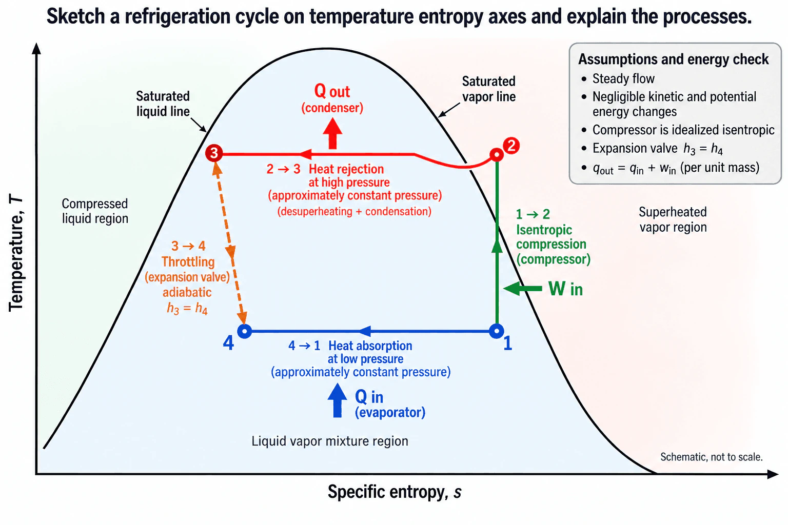
Draw temperature T on the vertical axis and specific entropy s on the horizontal axis. Add the saturation dome. Its left boundary is saturated liquid, its right boundary is saturated vapor, and the region inside contains a liquid vapor mixture.
State 1 is saturated vapor at low pressure. Process 1 to 2 is idealized isentropic compression. Compressor work enters the refrigerant, pressure and temperature rise, and entropy remains constant, so the path is vertical on T s axes. State 2 is superheated vapor.
Process 2 to 3 is heat rejection in the condenser at approximately constant high pressure. The refrigerant first desuperheats, then condenses through the two phase region. State 3 is saturated liquid in the idealized cycle. The condenser rejects qout.
Process 3 to 4 is throttling through the expansion valve. For a steady adiabatic valve with negligible kinetic and potential energy changes, the steady flow energy equation gives h3 = h4. Pressure and temperature decrease, and state 4 becomes a liquid vapor mixture. Entropy increases because throttling is irreversible.
Process 4 to 1 is heat absorption in the evaporator at approximately constant low pressure. The refrigerant absorbs qin and evaporates until it reaches saturated vapor at state 1.
The thermodynamic quantities have different meanings. Temperature describes thermal state. Heat is energy transferred because of a temperature difference. Internal energy is stored microscopic energy. Enthalpy, h = u + pv, is especially useful for steady flow devices. Entropy measures energy dispersal and irreversibility. Thermal power is heat transfer per unit time, while stored energy is energy contained within a control volume.
For the complete steady cycle, the first law gives qout = qin + win when these quantities are positive magnitudes per unit mass. Enthalpy is commonly reported in kJ/kg and entropy in kJ/(kg K). Property tables or validated refrigerant property software can check the state points and energy balance. Real compressors generate entropy, and real heat exchangers have pressure drops and finite temperature differences, so the actual cycle departs from this ideal sketch.
This tests whether the candidate can connect a refrigeration system to thermodynamic state changes, identify the compressor, condenser, expansion valve, and evaporator processes, and use temperature, entropy, enthalpy, heat, work, and energy balances consistently.
Common mistakes are placing the compressor inlet in the liquid vapor mixture region, placing the compressor discharge on the saturated vapor line instead of in the superheated region, drawing throttling as an isentropic process instead of an isenthalpic process, reversing heat or work directions, or treating the complete condenser path as isothermal even while the refrigerant is superheated. Another mistake is confusing entropy with enthalpy when describing the expansion valve.
Draw the four states first, then explain each process in sequence from 1 to 2 to 3 to 4 to 1. State the idealizations before using terms such as isentropic, constant pressure, or constant enthalpy. Finish with the cycle energy balance and one sentence explaining how a real cycle departs from the ideal sketch.


