This interview guide is for educational and informational purposes only. It is designed to help readers prepare, but it does not guarantee any interview result, hiring decision, offer, or outcome. Interview questions, hiring criteria, and preferred answers can vary by employer, interviewer, industry, location, and time. All answers, examples, and explanations in this guide are suggested examples for interview preparation, not definitive answers or instructions for professional practice. They are based on research and judgment, are provided without warranties of any kind, and should be adapted to the question, role, and applicable laws and professional requirements. Diagrams are simplified illustrations intended to highlight the main concepts and their relationships; actual situations, systems, and practices may be more complex. Alternative approaches may be equally valid or better suited to a particular question, context, or interviewer. To the fullest extent permitted by applicable law, the contributors and publisher are not liable for decisions made, actions taken, or losses incurred based on this guide.
State Laws and Professional Responsibilities
Laws and requirements governing an occupation vary by state and jurisdiction. You are responsible for checking the current laws, licensing requirements, and scope-of-practice rules that apply to your location and role, and for ensuring that your answers and actions comply with them. Adapt examples in this guide to those requirements. This guide is not legal advice.
Identity, Image, and Privacy Notice
To respect individual privacy, some names, profile photographs, avatars, biographical details, and other identifying information displayed in this guide may be replaced with pseudonyms, licensed stock images, illustrative avatars, composite images, or representative descriptions. Unless a person is expressly identified as an actual contributor, a displayed name, image, or profile should not be understood as depicting or identifying a specific candidate, interviewer, employee, or other real individual. These representations are provided for editorial and illustrative purposes only and do not imply endorsement, employment, participation, or affiliation with this guide or any company mentioned in it. Any resemblance to an actual person is coincidental.
Company Notice
This guide is an independent educational resource and is not affiliated with, endorsed by, sponsored by, or approved by the company named in this guide. Company names identify reported interview experiences or the employer context of clearly labeled original practice exercises. Interview practices can change without notice, and inclusion of company-specific content does not mean these questions are official, complete, or guaranteed to be asked. To the fullest extent permitted by law, the author, contributors, and publisher are not responsible for outcomes related to use of this material.
Content Accuracy and Verification
To the fullest extent permitted by applicable law, we do not represent or warrant that interview guides, questions, answers, examples, or diagrams are accurate, complete, current, error-free, or suitable for any particular purpose. You are responsible for independently reviewing and verifying the information before relying on it.
Questions or comments?
Contact us for general questions, or share feedback, technical corrections, and comments with the community.
11. How would you design a circuit with 5 inputs that counts the number of 1s among them using only Half Adders and Full Adders?System DesignMediumNvidia
i Question Details
Design a circuit that counts how many of five input bits are set to 1 while using only Half Adders and Full Adders.
Short Interview Answer (30-60 seconds)
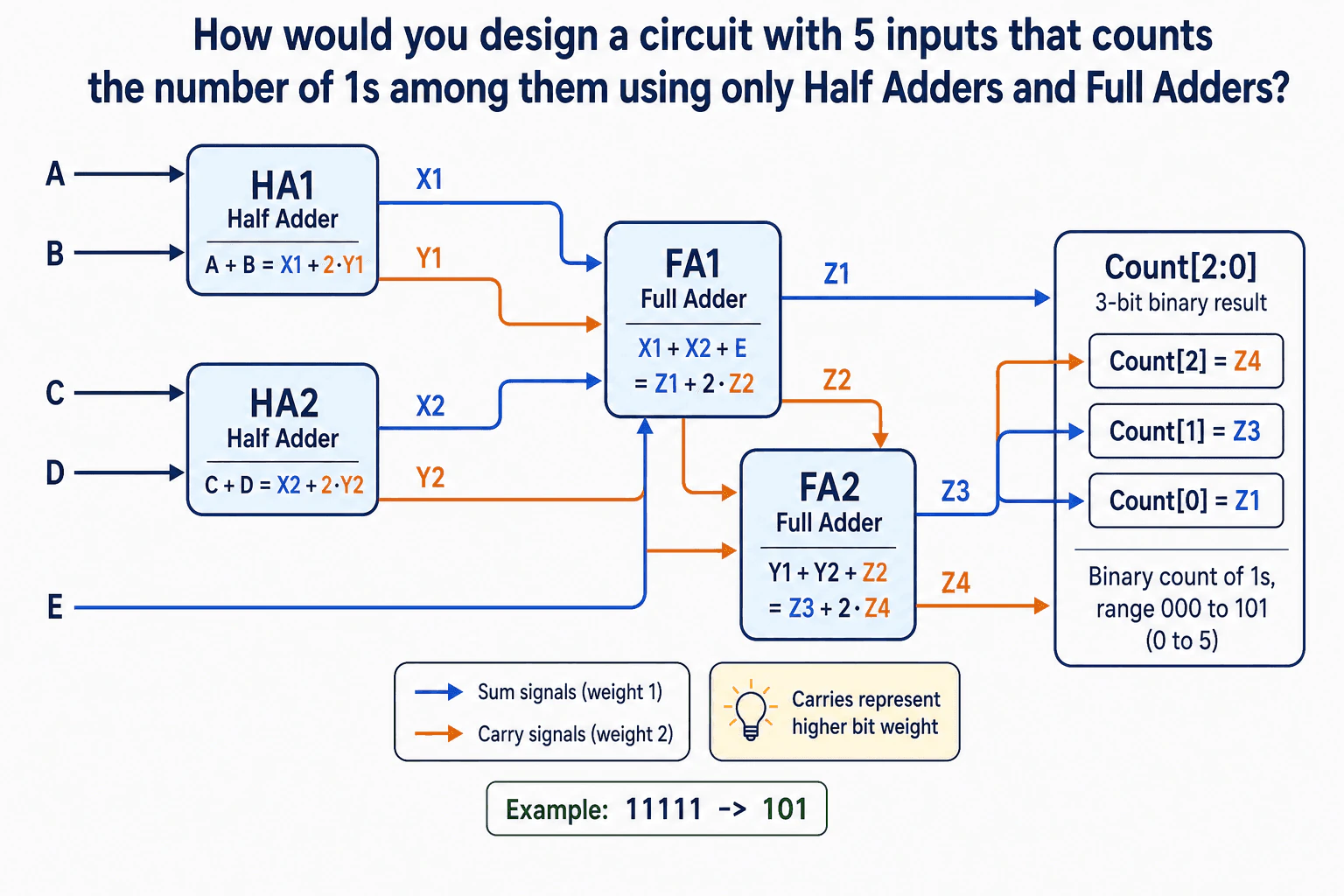
At a high level, the circuit must count how many of five input bits are 1. The main challenge is keeping each partial result at the correct binary place value. I would explain it in three stages. HA1 and HA2 first add two input pairs. FA1 combines their sum bits with E. FA2 then combines the carry bits. The final count is Count[2:0] = {Z4, Z3, Z1}. The trade-off is that the longest signal path passes through several adder stages.
Detailed Explanation
The goal is to take five one-bit inputs and produce a three-bit number that tells us how many inputs are 1. The answer can range from zero through five. The main challenge is keeping each partial result in the correct place value while combining the inputs. The diagram solves this in stages. It first adds A with B and C with D. Then it combines those two sums with E. Finally, it combines the carry values and places the three remaining bits into the final count.
Useful Questions to Ask the Interviewer
Should the result always be a three-bit count from 000 through 101?
Should I focus on this clear adder-tree design rather than minimizing the number of adders?
How to Explain It in an Interview
1. Add the first two input pairs
"I would first reduce four of the inputs into two smaller results."
HA1 adds A and B. It produces X1 as the sum and Y1 as the carry. The relationship is A + B = X1 + 2·Y1. X1 stays in the ones place. Y1 represents a value of two.
HA2 does the same for C and D. It produces X2 and Y2, so C + D = X2 + 2·Y2. At this point, X1 and X2 are ones-place values. Y1 and Y2 are twos-place values.
2. Combine the remaining ones-place values
"Next, I would add X1, X2, and the fifth input E."
FA1 takes X1, X2, and E. It produces Z1 as its sum and Z2 as its carry. The relationship is X1 + X2 + E = Z1 + 2·Z2.
Z1 remains in the ones place, so it becomes Count[0]. Z2 has weight two, so it must be combined with Y1 and Y2 rather than with another ones-place signal.
3. Combine the carry values
"Now I would add the three values that all belong to the twos place."
FA2 takes Y1, Y2, and Z2. It produces Z3 as its sum and Z4 as its carry. Because all three FA2 inputs already have weight two, Z3 also has weight two. Z4 moves one place higher and has weight four.
This gives Z3 for Count[1] and Z4 for Count[2].
4. Form the final three-bit count
"The final output is just the three remaining bits in their correct positions."
The diagram maps Count[0] = Z1, Count[1] = Z3, and Count[2] = Z4. Therefore, Count[2:0] = {Z4, Z3, Z1}.
The output range is 000 through 101, which represents decimal zero through five. That covers every possible number of 1s among five inputs.
5. Check a boundary case
"I would finish by testing the maximum possible count."
If A, B, C, D, and E are all 1, the input is 11111. The diagram shows the result as 101. Binary 101 is decimal five, so the circuit correctly reports five set inputs.
The design uses only Half Adders and Full Adders, as required. Its main downside is propagation delay. Some results must pass through several connected adders before the final count becomes stable.
Engineering Considerations / Design Trade-offs
The benefit is that the circuit is simple to reason about because every stage combines values with known place values. X1, X2, and E are ones-place values. Y1, Y2, and Z2 are twos-place values. FA2 then produces Z3 in the twos place and Z4 in the fours place. This makes the final mapping easy to verify. The downside is delay through the connected adders. A change at an early input may need to pass through more than one adder before Count[2:0] becomes stable. We accept that here because the design is small and clear.
Why Interviewers Ask This
The interviewer wants to see whether you can break a small hardware problem into clear steps. They are checking whether you understand Half Adders, Full Adders, carry signals, and binary place values. They also want to see whether you can prove that intermediate signals are combined at the correct weight. The key skill is reasoning about the circuit, not memorizing one fixed arrangement.
Interviewer may ask next
How would the design change if the circuit had six input bits instead of five?
I would keep the same basic idea and extend the adder tree. The important rule would stay unchanged: combine signals only with other signals that represent the same place value.
The first stages could still reduce pairs of one-bit inputs with Half Adders. Their sum outputs would remain ones-place values, while their carry outputs would become twos-place values. I would then use Full Adders to reduce the remaining ones-place signals. Any carries created there would join the twos-place group. If several twos-place signals remain, another adder would reduce them and could create a fours-place carry.
The final result would still need three bits because six in binary is 110. Correctness comes from tracking the weight of every intermediate signal through each stage. The downside is that the sixth input requires more adder hardware or another level in the tree, which can increase propagation delay.
Why does FA2 produce Count[1] and Count[2] instead of another ones-place sum and twos-place carry?
Because FA2 does not receive ordinary weight-one inputs. Its three inputs are Y1, Y2, and Z2, and each already represents a value in the twos place.
Y1 is the carry from HA1. Y2 is the carry from HA2. Z2 is the carry from FA1. A carry from those earlier additions represents two, not one. FA2 therefore adds three weight-two values.
Its sum output Z3 stays at the same weight as its inputs, so Z3 represents the twos place and becomes Count[1]. Its carry output Z4 moves one binary position higher, so it represents the fours place and becomes Count[2]. Z1 remains the ones-place result and becomes Count[0]. The downside is that this weighting is easy to explain incorrectly unless every signal's place value is tracked carefully.
12. How would you design a one-hot vector system that zeros out all bits to the right of the first detected 1?System DesignMediumNvidia
i Question Details
Design a one-hot vector circuit that keeps the most-significant 1 and clears all lower-order bits to its right.
Short Interview Answer (30-60 seconds)
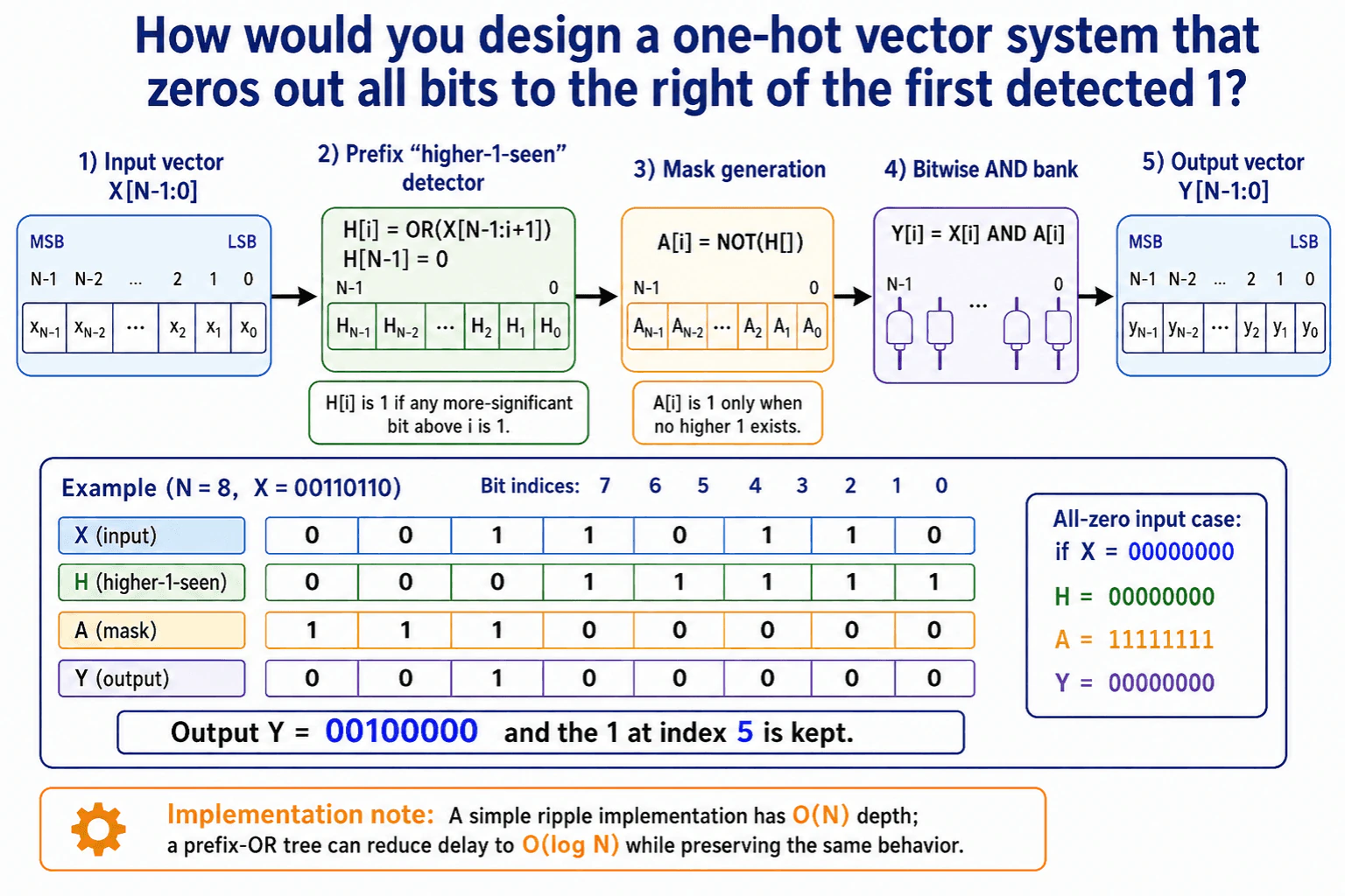
At a high level, the goal is to keep only the most-significant 1 in the input vector. The main challenge is knowing whether a higher bit is already set before deciding each output bit. I would explain the design in three steps: detect whether a higher 1 exists, build a mask, and apply that mask to the input. A simple ripple version has O(N) logic depth. A prefix-OR tree reduces the delay to O(log N), but uses more parallel logic.
Detailed Explanation
The system receives a bit vector and must keep only its leftmost, or most-significant, 1. Every 1 to the right of that bit must become 0. The difficult part is deciding each output bit while knowing whether any more-significant bit is already 1. The diagram solves this with a higher-1-seen vector, then turns that information into a mask. Finally, it ANDs the mask with the original input. This gives one output bit when the input contains at least one 1, and gives all zeros for an all-zero input.
Useful Questions to Ask the Interviewer
Should the most-significant bit always have priority?
How wide can the input vector become?
Is combinational delay more important than using less logic?
How to Explain It in an Interview
1. Start with the input and priority rule
I would say that the left side has higher priority than the right side. The input is X[N-1:0], where N-1 is the most-significant bit. We want Y to contain the first 1 found when scanning from the most-significant side. Every lower bit must be cleared.
For the example X = 00110110, the first 1 appears at index 5. The required output is therefore Y = 00100000.
2. Build the higher-1-seen vector
The next step is the Prefix "higher-1-seen" detector. For each position i, H[i] tells us whether any more-significant bit above i is already 1.
The diagram defines H[i] as OR(X[N-1:i+1]). For the highest position there is nothing above it, so H[N-1] = 0. In the example, H becomes 00011111. Once the 1 at index 5 has been passed, every lower position knows that a higher 1 already exists.
3. Turn that information into a mask
Next, the design creates A[i] = NOT(H[i]). The mask stays 1 only while no higher 1 has been seen.
For the example, A becomes 11100000. This mask still allows index 5 because H[5] is 0. It blocks every position below index 5 because those positions have H[i] = 1.
4. Apply the mask to the original input
The Bitwise AND bank computes Y[i] = X[i] AND A[i]. This is important because the mask alone is not one-hot. It can contain several leading 1s.
ANDing it with X keeps the first real 1 from the input and removes all lower 1s. For X = 00110110, the final result is Y = 00100000.
5. Handle the all-zero case and timing trade-off
For an all-zero input, H is 00000000 and A is 11111111. The final AND still produces Y = 00000000, so no special output fix is needed.
A simple ripple implementation can build the prefix result one position at a time. Its logic depth is O(N). For a wider vector, a prefix-OR tree can compute the same higher-1 information in O(log N) depth. The benefit is lower delay. The downside is more parallel logic and wiring.
Engineering Considerations / Design Trade-offs
The benefit of this design is that every output bit follows one clear rule. The higher-1-seen vector tells us whether a more-important bit already contains 1. The mask then blocks lower positions, and the final AND keeps only a real input bit. A simple ripple implementation is easy to build, but its delay grows with N because information moves across the vector step by step. A prefix-OR tree reduces that delay to O(log N). The downside is that the tree needs more parallel logic and more wiring. We would choose between them based on vector width and timing needs.
Why Interviewers Ask This
The interviewer wants to see whether you can turn a small bit-manipulation requirement into clear logic. They are checking whether you understand priority, prefix operations, masking, and edge cases such as an all-zero input. They also want to see whether you can compare a simple O(N) implementation with a faster O(log N) tree and explain the trade-off without making the design harder than necessary.
Interviewer may ask next
How would you change the design if the vector became very wide and the O(N) ripple delay was too slow?
I would keep the same higher-1-seen, mask, and final AND idea, but I would change how H is calculated. Instead of letting the OR result move across the vector one position at a time, I would use a prefix-OR tree. The tree combines groups of bits in parallel, then combines those partial results until each position knows whether any more-significant bit is 1.
The rest of the design does not change. We still compute A[i] = NOT(H[i]), then Y[i] = X[i] AND A[i]. Because the meaning of H stays the same, the output remains correct for every input.
The main benefit is timing. The logic depth falls from O(N) to O(log N), which matters for large N. The downside is extra parallel gates, more wiring, and a more complex physical layout.
How does the design behave when the input vector contains no 1 bits?
The same logic already handles that case correctly. If X is all zeros, no position ever sees a higher 1. That makes every H bit 0. The mask A is the inverse of H, so A becomes all ones.
At first, an all-ones mask may look unusual, but the final Bitwise AND bank makes the result correct. Every output bit is Y[i] = X[i] AND A[i]. Since every X bit is 0, every Y bit is also 0. For the eight-bit example, X = 00000000 gives H = 00000000, A = 11111111, and Y = 00000000.
The benefit is that we do not need a separate special-case path. The downside is only that the intermediate mask is not itself one-hot, so the final AND step is essential.
13. How would you design a circuit that counts 1 every time another counter counts from 0 to 255?System DesignMediumNvidia
i Question Details
Design the counter interaction so one counter increments whenever the faster counter completes a 0-to-255 cycle.
Short Interview Answer (30-60 seconds)
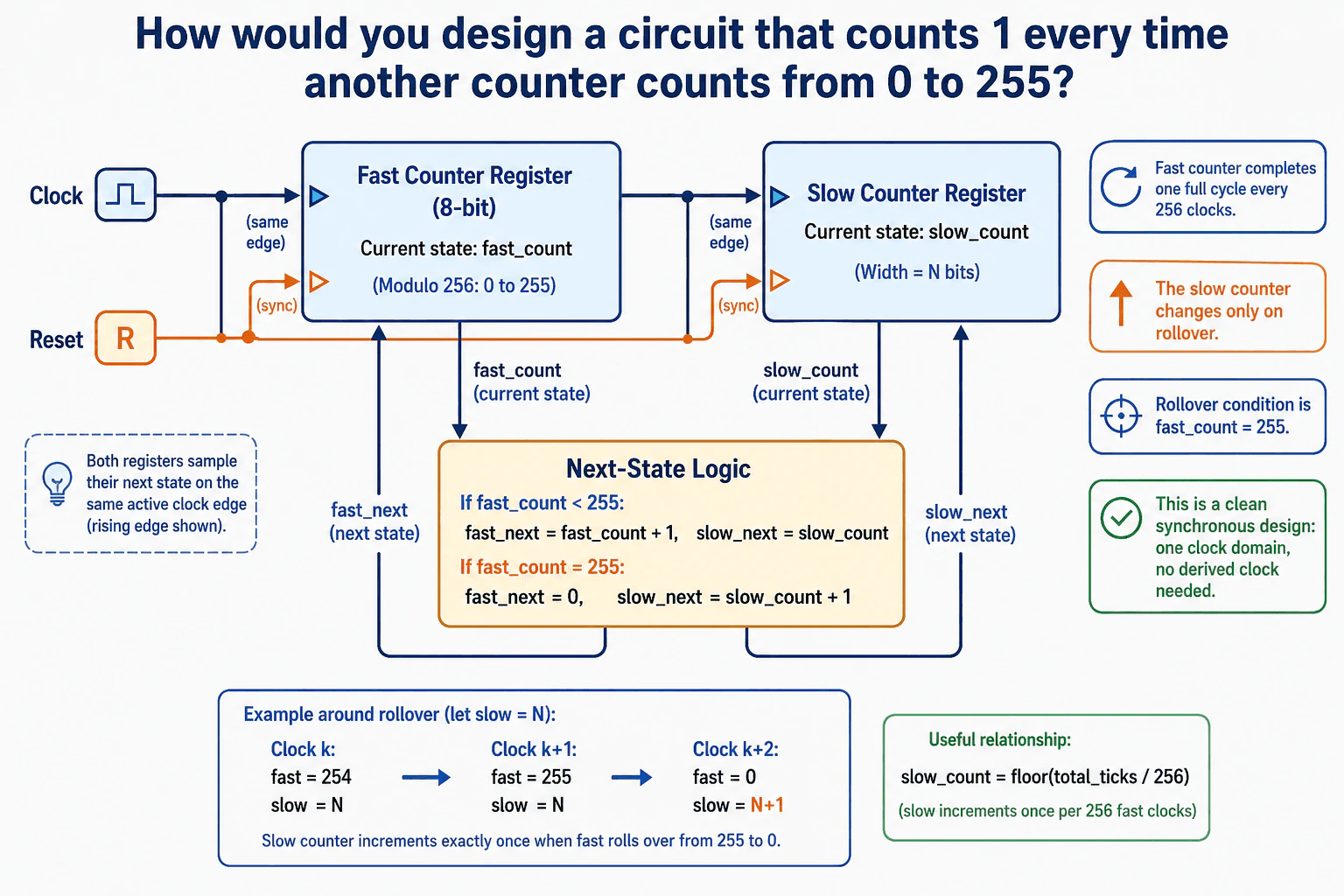
At a high level, I would keep both counters on one shared clock. The fast counter counts from 0 to 255. The slow counter moves up once when the fast counter rolls over. The main challenge is that the slow counter must change only on rollover, not on every clock. I would explain the design in two flows: the shared clock and reset, and the next-state logic that updates both counters together. The trade-off is a little more logic in the middle, but the design stays clean and synchronous.
Detailed Explanation
The goal is to make one count go up every time another count finishes one full round from 0 to 255. The hard part is that the second count must move only once, right when the first one wraps around. The diagram solves this with one shared clock, one shared reset, two counters, and a small block in the middle that chooses the next value for each counter. That keeps the design simple and easy to explain in an interview.
Useful Questions to Ask the Interviewer
Should reset be synchronous, or should it clear both counters immediately?
Do you want the slow counter to start at zero after reset, or keep a saved value?
How to Explain It in an Interview
1. Explain the goal and the main idea
At a high level, I would keep both counters on one shared clock. The fast counter counts from 0 to 255. The slow counter moves up once when the fast counter rolls over.
That is the main idea in the diagram. The slow counter does not watch the fast value all the time. It only changes when the fast count wraps from 255 back to 0. That makes the design easy to reason about.
2. Explain the shared clock and reset
Both counters sample on the same active clock edge. The diagram also shows one reset line going to both blocks.
This matters because both counters start together and move together. A synchronous reset keeps the starting point clean. It also avoids a second clock for the slow counter. That is important because one clock domain is safer and easier to test.
3. Explain the next-state logic
The middle block is the key part. It looks at the current fast count and decides the next values.
If fast_count is below 255, fast_next becomes fast_count + 1, and slow_next stays the same. If fast_count is 255, fast_next becomes 0, and slow_next becomes slow_count + 1. That means the slow counter changes only on rollover. It does not change on any other fast count.
4. Explain the example around rollover
The example at the bottom makes the timing very clear. At clock k, the fast counter is 254 and the slow counter is N. At clock k+1, the fast counter is 255 and the slow counter is still N. At clock k+2, the fast counter becomes 0 and the slow counter becomes N+1.
That example shows the whole point of the design. The increment happens exactly once for each full 0-to-255 cycle. The fast counter returns the new fast value, and the slow counter returns the new slow value after the same clock edge.
5. Explain the trade-off
The main trade-off is a little more logic in the middle, but the benefit is a clean synchronous design. Both counters stay on the same clock, so there is no derived clock and no clock-skew problem.
The downside is that the compare logic must be correct. If the rollover check is wrong, the slow counter will miss or add counts. I would accept that small extra logic because it keeps the design simple, clear, and reliable.
Engineering Considerations / Design Trade-offs
The benefit is that both counters stay on one clock. That makes the design easy to test and easy to keep in step. The slow counter changes only on rollover, so it does not need a second clock. The downside is that the middle logic must be correct, because one wrong compare would make the slow counter miss or add counts. The reset line also has to be handled carefully so both counters start from the same place. We accept that small extra logic because the design is much cleaner than using a derived clock.
Why Interviewers Ask This
Interviewers want to see whether you can turn a simple rule into a clean synchronous design. They are checking if you understand shared clocks, reset, rollover, and next-state logic. They also want to hear that you can explain why the slow counter changes only once per full cycle. The main signal is judgment: can you keep the design simple, correct, and easy to test?
Interviewer may ask next
What if the slow counter should increment every 16 fast cycles instead of every 256?
I would keep the same basic design, but I would change the rollover point. The fast counter would no longer need to run all the way to 255 before the slow counter moves. Instead, the middle logic would watch for 15, or I would use a 4-bit fast counter that naturally wraps after 16 counts.
The rest of the design stays the same. Both counters still share the same clock and reset. The fast counter still feeds the next-state logic, and the slow counter still changes only when the fast counter wraps.
That keeps the design correct and easy to explain. The downside is that the fast counter width or compare value must match the new cycle length very carefully. A wrong compare would make the slow counter drift from the intended rate.
What if reset must clear both counters immediately instead of waiting for the clock edge?
I would keep the same counters, but I would make the reset behavior asynchronous. That means the reset line would clear both counters right away, instead of waiting for the next clock edge.
The clock and next-state logic would stay the same. Only the reset handling inside both registers would change. The fast counter would go back to zero, and the slow counter would go back to zero at once.
This can be useful when the system must start in a known state very quickly. The downside is that asynchronous reset release needs more care, because the counters can come out of reset at slightly different moments if the signal is noisy or poorly timed. That makes the design a little harder to verify.
14. How would you design a system that outputs 1 whenever an infinite LSB-first bit stream represents a value divisible by 5?System DesignMediumNvidia
i Question Details
Design the state machine for an infinite bit stream and explain how you track divisibility by 5.
Short Interview Answer (30-60 seconds)
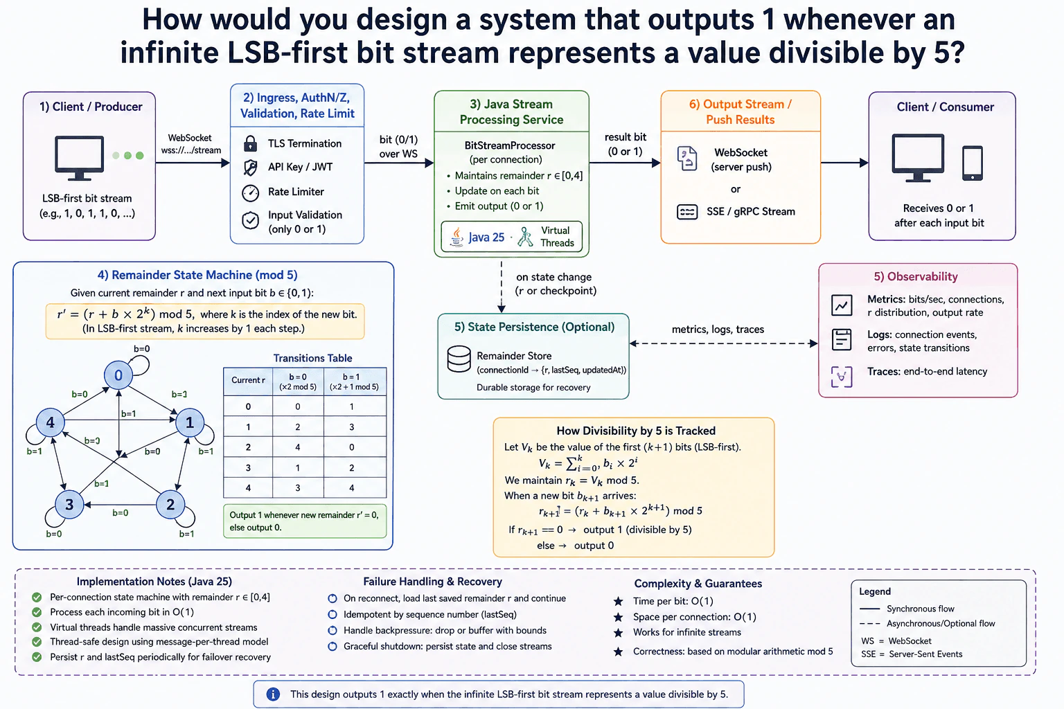
At a high level, this is a streaming state problem. The system must read an endless LSB-first bit stream and say 1 whenever the number so far is divisible by 5. The hard part is that the input never ends, so the service must stay correct for every new bit and keep tiny state. I would explain it in three parts: input checks, the Java processor with the mod-5 state machine, and the output plus recovery path. The trade-off is a little state per stream for very fast answers.
Detailed Explanation
A client sends bits one by one. After each bit, the system must say whether the number built so far is divisible by 5. The hard part is that the input never ends, so the service cannot wait for the full number. It must keep only a tiny piece of memory and update it for every new bit. The diagram shows a clean path: checks at the edge, a Java service in the middle, and a result sent back right away.
Useful Questions to Ask the Interviewer
Should the service return a result after every bit, or only when the stream ends?
Do we need to keep state after reconnects, and should old sequence numbers be rejected?
How to Explain It in an Interview
1. Explain the goal and the main idea
At a high level, the goal is simple. We take an infinite stream of bits, and after each bit we say whether the value so far is divisible by 5. The tricky part is that the value never ends, so we cannot store the full number. The diagram solves this by keeping a tiny running remainder and by sending one output bit back for each input bit.
2. Explain the input path
For the input path, the client sends bits over WebSocket. The edge layer does TLS termination, API key or JWT checks, rate limiting, and input validation. That means only 0 or 1 is allowed into the service. This keeps bad traffic away from the Java processor and makes the main logic easier to trust.
3. Explain the Java processor and the mod-5 state machine
The core of the design is the BitStreamProcessor inside a Java 25 service. The diagram keeps one state machine per connection. It stores the current remainder r in the range 0 to 4. After each new bit, it updates r and emits 1 only when r becomes 0. The math is simple: each new bit has weight 2^k, so the new remainder is computed with mod 5. Because 2^4 = 16 and 16 has the same remainder as 1 when divided by 5, only the last four bit positions matter. That is why the diagram also tracks position mod 4. Virtual threads help the service handle many active streams without blocking the whole JVM.
4. Explain output and recovery
The output path is also a stream. The service pushes the result bit back through WebSocket, or through SSE or a gRPC stream. That keeps the client in sync with the incoming bits. The optional Remainder Store saves {connectionId, r, lastSeq, updatedAt} when the state changes or when the service takes a checkpoint. If a client reconnects, the service can load the last saved remainder and continue from there.
5. Explain scale, failures, and trade-offs
For scale, the key point is that each active stream keeps only O(1) state. That is a good fit for an infinite stream. The service still needs backpressure, so it can drop or buffer work with bounds if traffic grows too fast. The observability box shows metrics, logs, and traces, which helps track bit rate, errors, and state distribution. The main trade-off is simple: keeping per-stream state makes the answer fast and easy to reason about, but recovery and persistence add some extra work.
Engineering Considerations / Design Trade-offs
The benefit is that every bit takes O(1) time. The processor does one small update and one simple check, so it stays fast even for an endless stream. The space cost is also O(1) per connection, because the service only keeps the remainder, the bit position, and a few bookkeeping fields. That is a strong fit for this problem. The downside is that the service must keep state between bits and save checkpoints if a connection can drop. Backpressure is also important, because too many active streams can still fill memory if buffering is too large.
Why Interviewers Ask This
Interviewers want to see if you can turn a math rule into a clean streaming design. They are checking whether you can keep the state tiny, separate input checks from core processing, and explain why the output can be sent right away after each bit. They also want to hear good judgment about recovery, backpressure, and observability. That shows you can build a simple answer from a tricky stream problem.
Interviewer may ask next
What if a client disconnects and later resumes the same bit stream?
I would keep the same basic design, but I would make reconnection part of the state story. The BitStreamProcessor still owns one remainder state per connection, and the Remainder Store keeps {connectionId, r, lastSeq, updatedAt}. When the client reconnects, the service loads the last saved remainder and starts from the next sequence number. That keeps the math correct because we continue from the exact point where the stream stopped. If the client sends bits again after a disconnect, the lastSeq check lets the service reject the same request sent again. The output stream then continues normally, bit by bit, without guessing or recomputing from the start. The downside is a little more storage and more bookkeeping, but the stream stays correct and easy to recover.
What if the number of active streams grows much faster than expected?
I would keep the same architecture, but I would put more pressure control around it. The WebSocket ingress would keep the TLS, auth, and rate limits, and the BitStreamProcessor would still handle one tiny state machine per connection. The main change would be stricter backpressure, so the service buffers only a small amount of work and then slows down or drops extra load in a controlled way. Virtual threads still help because they let the JVM wait on many streams without tying up platform threads, but they do not remove the need for limits. Observability becomes more important too, because metrics and traces can show when the stream rate is rising. The downside is that the service may accept less work during spikes, but the per-stream answers stay correct.
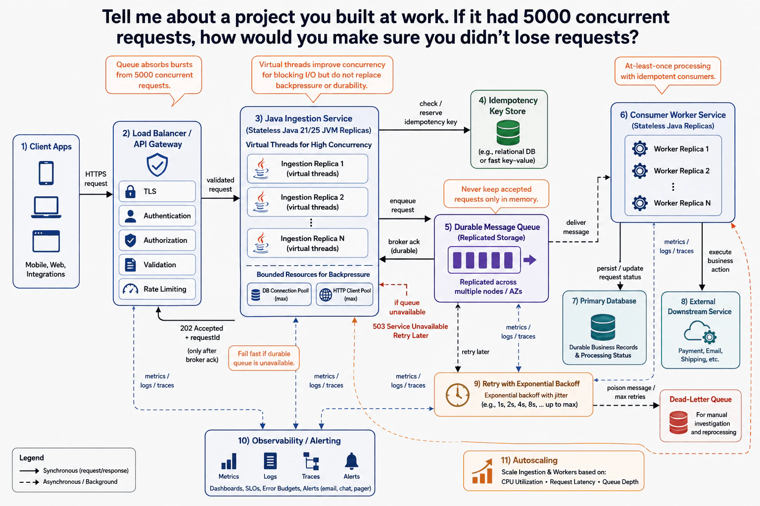
15. Tell me about a project you built at work. If it had 5000 concurrent requests, how would you make sure you didn’t lose requests?System DesignMediumNvidia
i Question Details
Describe a project you built at work and explain how you would keep requests from being lost if traffic reached 5000 concurrent requests.
Short Interview Answer (30-60 seconds)
One project I built was a request-processing service that accepted client work and finished the slower business work in the background. The main challenge at 5000 concurrent requests is never telling a client that work was accepted before it is stored safely. I would explain it in three flows: request acceptance, durable queueing, and worker processing. The Java service returns 202 only after the queue confirms the write. Workers then process messages with retries. The downside is more operational complexity.
Detailed Explanation
The project is a service where clients send work that may take longer to finish. The most important rule is simple: if we tell the client that we accepted the work, we must not lose it afterward. With 5000 requests arriving at the same time, the system also cannot let slow work overload everything else. I would solve this by separating the fast step that safely accepts each request from the slower step that completes the work. I would then explain how retries, failures, and scaling are handled.
Useful Questions to Ask the Interviewer
Does the client need the final business result immediately, or is a 202 Accepted response okay?
Can clients retry the same request if they do not receive a response?
How long should failed messages remain available for retry or investigation?
How to Explain It in an Interview
1. Protect the entry point
I would say, "I first protect the system before the request reaches my application." Client Apps send an HTTPS request through the Load Balancer / API Gateway. The gateway handles TLS, Authentication, Authorization, Validation, and Rate Limiting.
The validated request then reaches the Java Ingestion Service. It runs as stateless Java 21/25 JVM replicas. Virtual threads help each JVM handle many blocking requests, but they do not create unlimited database or network capacity. Bounded DB Connection Pool and HTTP Client Pool limits provide backpressure, which means the service limits work before resources are exhausted.
2. Accept the request only after durable storage
For the request-acceptance path, the Java Ingestion Service checks or reserves an idempotency key. Idempotency means the same logical request can be sent again without creating the business action twice.
The service then enqueues the request in the Durable Message Queue. The queue uses replicated storage across multiple nodes or availability zones. The Java service waits for the durable broker acknowledgement. Only after that acknowledgement does it return 202 Accepted + requestId to the client.
If the Durable Message Queue is unavailable, the service fails fast. It returns 503 Service Unavailable and the client can retry later. This avoids keeping accepted requests only in JVM memory.
3. Process the saved work with workers
The Durable Message Queue delivers messages to the Consumer Worker Service. These workers run as separate stateless Java replicas, so ingestion and business processing can scale independently.
A worker executes the business action against the External Downstream Service. It also persists or updates the request status in the Primary Database. This database stores durable business records and processing status.
4. Handle retries and duplicate delivery
The design uses at-least-once processing, so a message can sometimes be delivered more than once. Consumers therefore need idempotent, or duplicate-safe, processing so repeated delivery does not repeat the business effect.
For a transient failure, Retry with Exponential Backoff waits longer between attempts before trying again. If the message still fails after the maximum retries, it moves to the Dead-Letter Queue for investigation and reprocessing.
5. Scale and watch the system
I would autoscale the Java Ingestion Service and Consumer Worker Service using CPU utilization, request latency, and queue depth. The queue absorbs bursts, while rate limits and bounded resource pools protect limited dependencies.
Observability / Alerting collects metrics, logs, traces, and alerts from the important parts of the flow. The benefit is that accepted work is stored safely before success is returned. The downside is extra queue, retry, monitoring, and duplicate-handling complexity.
Engineering Considerations / Design Trade-offs
The benefit is that a request is stored safely before the client receives a successful acceptance response. The queue can also absorb a burst of 5000 concurrent requests while workers process the slower work at their own pace. The downside is more moving parts. We need a durable queue, workers, retries, a Dead-Letter Queue, monitoring, and duplicate-safe processing. Virtual threads help the Java service handle many blocking requests, but they do not remove database or network limits. Rate limits and bounded resource pools are still needed to stop the system from taking more work than it can safely handle.
Why Interviewers Ask This
The interviewer wants to see whether you can protect accepted work during a large traffic spike. They also want to know whether you understand the difference between accepting a request and finishing its business work. A strong answer shows judgment about durable storage, duplicate requests, retries, backpressure, independent scaling, and failure handling. They are also checking whether you can explain these choices and their downsides clearly.
Interviewer may ask next
What would you change if clients retried aggressively whenever they did not receive the 202 Accepted response?
I would keep the same basic design, but the Idempotency Key Store becomes especially important. The client should send the same idempotency key when retrying the same logical request. The Java Ingestion Service checks or reserves that key before creating new queued work.
This protects the case where the first request reached the Durable Message Queue, but the client never received the 202 response. A retry should not create a second independent business action for the same request.
The Consumer Worker Service also needs idempotent, or duplicate-safe, processing. The queue provides at-least-once processing, so the same message can be delivered again even without a client retry.
The downside is extra state and logic around duplicate detection. The idempotency information must remain available long enough to cover realistic retry periods, and the business action must safely handle repeated delivery.
What happens if the External Downstream Service is unavailable for several minutes?
I would keep accepting requests while the Durable Message Queue remains healthy and has enough capacity. The Java Ingestion Service can still return 202 after the broker confirms that the request is safely stored. The unavailable External Downstream Service does not block the request-acceptance path.
When the Consumer Worker Service tries the business action and gets a transient failure, the message follows Retry with Exponential Backoff. The waits become longer between attempts, which avoids repeatedly hitting a failing dependency.
If the message reaches the maximum retry count, it moves to the Dead-Letter Queue. The team can investigate it and reprocess it later.
The main downside is growing queue depth and longer processing delay. Autoscaling can add workers, but adding workers cannot fix an External Downstream Service that is itself unavailable.
16. Pipeline based architecture of CPU GPU architecture components Life of triangleSystem DesignMediumNvidia
i Question Details
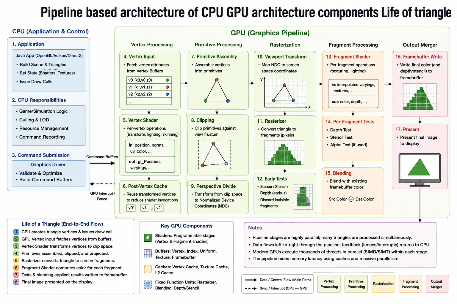
Describe the CPU/GPU pipeline architecture, the key components involved, and how a triangle flows through the pipeline.
Short Interview Answer (30-60 seconds)
At a high level, this is a graphics pipeline that turns triangle data into pixels on the screen. The main challenge is that the Java app must prepare work correctly, while the graphics chip must draw many small pieces very fast. I would explain it in three parts: how the Java side sends commands, how the triangle moves through the GPU stages, and how the finished frame is written and shown. The trade-off is speed versus extra sync and memory movement.
Detailed Explanation
The question asks how one triangle becomes the final picture on the screen. The hard part is that the program must set things up correctly, while the graphics chip must draw many tiny pieces fast. We also need to keep the work moving in order, or the image will be wrong. The diagram breaks the answer into parts: how the Java side sends the work, how the triangle moves through the graphics stages, and how the finished image is written and shown.
Useful Questions to Ask the Interviewer
Should I keep the answer to the standard triangle pipeline, or also mention optional stages like tessellation and geometry if you want deeper coverage?
Do you want me to stay framework-neutral, or should I speak in Java terms like a Java app using OpenGL, Vulkan, or DirectX bindings?
How to Explain It in an Interview
1. Explain the goal and the main idea
At a high level, the goal is simple. We start with triangle data and end with pixels on the screen. The CPU handles setup. The GPU handles the repeated drawing work. That split matters because the chip can do the same math on many small pieces. In this diagram, the Java app and driver prepare commands first, then the triangle flows through the GPU pipeline, and finally the image is shown on the display.
2. Explain the Java side and command submission
For the create path, the Java app builds the scene, sets shader and texture state, and issues draw calls. The CPU also does culling, level-of-detail choices, and resource management. Then the graphics driver validates the work and builds command buffers. That matters because the GPU should get one clean batch of work. The dashed sync line back to the CPU shows that the app can wait on a fence or interrupt when needed.
3. Explain how the triangle moves through the GPU
The first GPU step is Vertex Input. It fetches vertex data from vertex buffers. The Vertex Shader transforms each vertex and can add lighting. The Post-Vertex Cache can reuse results. Primitive Assembly joins the vertices into a triangle. Clipping removes parts outside the view. Perspective Divide and Viewport Transform move the triangle into screen space. Rasterizer then turns the triangle into fragments, which are small pixel candidates. Early Tests can drop fragments that are invisible.
4. Explain fragment work and the final frame
Fragment Shader runs per fragment. It can sample textures and compute color. After that, Per-Fragment Tests check depth, stencil, and alpha. Those tests keep invalid pixels from overwriting visible ones. Blending mixes the new color with what is already in the framebuffer. Framebuffer Write saves the final result. Present sends the finished image to the display. That is the end of the triangle’s life.
5. Explain memory, parallelism, and trade-offs
The diagram also shows GPU memory. Vertex, index, uniform, texture, depth, and framebuffer data live there. Shader cores, texture units, rasterizer units, ROPs, and caches do the fast work on chip. The main trade-off is speed versus extra setup and sync. The design is fast because the GPU does the heavy work in parallel. The downside is that the CPU and GPU are separate, so data movement and wait points add complexity.
Engineering Considerations / Design Trade-offs
The benefit is that the GPU can do the same math on many vertices and fragments in parallel, so it draws much faster than the CPU alone. The downside is that the CPU and GPU are separate, so commands and data must cross that boundary. That adds setup work and sync points. The post-vertex cache helps reduce repeat work, but it is not perfect. Another trade-off is latency. A triangle must pass many stages before the final frame appears, so the picture does not show up instantly for every frame.
Why Interviewers Ask This
Interviewers want to see if you can break one graphics problem into simple steps and keep the CPU and GPU roles clear. They are checking whether you know the fast path, the background work, and the point where the final image is produced. They also want judgment about caching, sync, and trade-offs, not just stage names.
Interviewer may ask next
What if the scene has many more triangles each frame?
I would keep the same pipeline, but I would make the CPU do more culling and level-of-detail work before it sends commands. That changes the Java app, the command recording step, and how much data goes into the vertex and index buffers. The goal is to send less useless work to the GPU. The GPU still runs the same vertex, raster, and fragment stages. Correctness stays the same because the pipeline does not change, only the amount of work changes. The downside is more CPU work and more tuning. If the scene is still heavy, the GPU can remain the bottleneck, especially in the fragment stage. It also makes frame time less stable if the scene changes a lot from frame to frame.
How would you keep the frame correct if the CPU must know when the GPU is done?
I would keep the same design and rely on the sync path shown in the diagram. The Java app submits command buffers, then it does not reuse the same GPU data too early. The GPU finishes the work and signals back with a fence or interrupt. That keeps the frame safe because the CPU and GPU do not step on the same buffers at the same time. In simple words, the CPU hands off the work, then waits only where needed. The downside is that too much waiting can reduce smoothness, so I would use the smallest safe sync point and keep the pipeline full. If the wait is too long, the frame rate can drop even when the GPU is still working correctly.
17. How would you design interface for linkedlist with different functions?API DesignMediumNvidia
i Question Details
Design a linked-list interface and explain the core operations, extensibility, and how callers would use the contract.
Short Interview Answer (30-60 seconds)
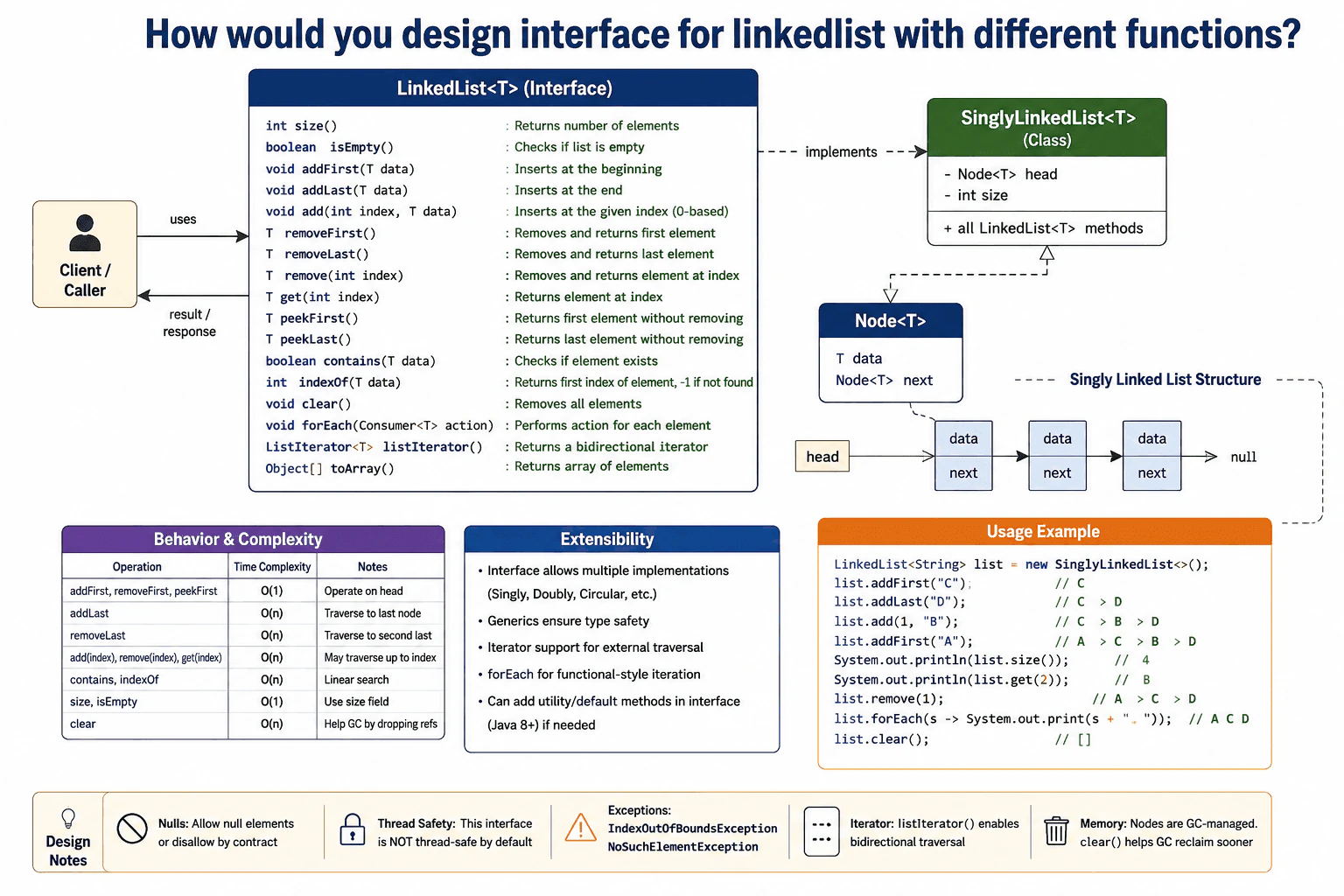
At a high level, I would define a LinkedList<T> contract with the common list operations, then let concrete classes like SinglyLinkedList<T> implement it. Callers depend on the interface, not the storage details. That keeps the API simple for add, remove, get, iterate, size, and clear. The main trade-off is that a singly linked list is light on memory and easy to update at the ends, but indexed access and search still need a walk through the nodes.
Detailed Explanation
This question asks how I would define one shared rulebook for a list of items. The goal is to let callers use the same list actions while the inside storage can change later. The main challenge is to keep the contract small, clear, and easy to extend for future list types and future features. I will follow the diagram by first explaining the LinkedList<T> contract, then the SinglyLinkedList<T> implementation, then the node shape, the caller example, and the trade-offs.
Useful Questions to Ask the Interviewer
Should null elements be allowed, or rejected by contract?
Do you want only a singly linked list, or future doubly and circular versions too?
Should the iterator support moving both forward and backward?
Must this be thread-safe, or is single-threaded use acceptable?
What exceptions should invalid indexes and empty-list removals throw?
How to Explain It in an Interview
1. Start with the contract
I would start by saying the interface is the public promise. It tells callers what a list can do. In the diagram, that contract is LinkedList<T>. It keeps the common actions in one place: add, remove, read, search, iterate, clear, and size. That is important because callers should depend on names and behavior, not on how the list stores data.
2. Show the concrete implementation
Next, I would point to SinglyLinkedList<T>. This class owns the real storage. It keeps a head reference and a size field. The diagram shows that it implements all LinkedList<T> methods. That means the caller can swap implementations later without changing the caller code. The interface stays stable, while the storage strategy can change.
3. Explain the node shape
Then I would explain Node<T>. Each node stores T data and a next link. The list starts at head and follows next links until null. That is why the structure is simple and memory-light. It is also why some operations need a walk through the list. The diagram also notes that the interface could later support doubly or circular lists, which is why the contract is the real center of the design.
4. Walk through the main operations
I would then explain the common methods one by one. addFirst, removeFirst, peekFirst, and size are natural fits for a linked list. addLast, get(index), remove(index), contains, and indexOf are also useful, but some of them may need traversal. forEach gives a clean way to loop through values. listIterator() supports external traversal, and toArray() helps when callers want an array view.
5. Explain complexity and caller usage
The complexity table shows the main trade-off. End operations are fast. Indexed operations usually need a walk through the nodes. That is fine for a simple linked list. The caller example makes this easy to understand: create the list, add values, read by index, remove one item, iterate, and clear it at the end. I would also mention the design notes: null handling should be a clear contract choice, the list is not thread-safe by default, and invalid indexes should throw common Java exceptions like IndexOutOfBoundsException or NoSuchElementException.
6. Finish with extensibility and trade-offs
I would close by saying the benefit of this design is clean separation. The interface gives one stable API. The implementation can change later. The downside is that some operations are linear time on a singly linked list, and that is the cost of keeping the structure simple. Still, for an interview answer, this is a solid design because it is easy to understand, easy to use, and easy to extend.
Practical Complexity & Trade-offs
I would keep the interface small and focused on the operations most callers need. The benefit is that one contract can support different list types later, such as singly, doubly, or circular lists, without changing the caller code. The downside is that some methods, like get(index) and remove(index), are slower on a singly linked list because the list must walk node by node. This is still a good trade-off because it stays simple, uses little extra memory, and is easy to test and explain in an interview. Clear rules for nulls, exceptions, thread safety, and iteration also reduce confusion and make the API easier to use correctly.
Why Interviewers Ask This
Interviewers ask this to see whether I can separate the public API from the internal storage. They want to know if I choose the right methods, explain common Java behavior, and keep the contract easy for callers. They also check whether I can talk about trade-offs clearly, especially linear scans, exception choices, null handling, and future extension to other list shapes. A strong answer shows judgment, not just method names. It shows that I understand how to design an API that is simple today and flexible tomorrow.
Interviewer may ask next
How would you change this if the list had to be thread-safe?
I would keep the same LinkedList<T> contract, but I would change the implementation strategy. The affected part is SinglyLinkedList<T>, not the caller-facing API. I would either wrap access with locking or provide a separate synchronized implementation. That keeps correctness because only one thread updates the structure at a time, and readers do not see half-finished changes. The downside is extra overhead and more contention, especially for add, remove, and iteration. I would also be careful with iterator behavior, because a thread-safe list still needs a clear rule for concurrent updates. I would probably say that the iterator is weakly consistent or externally synchronized, depending on the contract. The public API stays stable, but the implementation becomes safer, a little slower, and easier to reason about under load in practice overall.
How would you support a doubly linked list without changing the caller code?
I would keep the LinkedList<T> interface exactly the same and add a new DoublyLinkedList<T> implementation. The affected part is the storage inside the class, where each node would keep both prev and next links instead of only next. That makes removeLast() and backward traversal easier, and it can make some operations faster because the list can move in both directions. The caller still sees the same contract, so existing code does not change. The downside is more memory per node and more pointer updates on insert and delete. I would use this when the workload needs frequent tail operations or bidirectional iteration, and I would keep SinglyLinkedList<T> for simpler, lighter cases. The main idea is that the API stays stable while the internal shape changes over time for all callers.
18. How would you design a question on throttling?API DesignMediumNvidia
i Question Details
Design an API or contract that addresses throttling behavior and explain how clients would know when to back off.
Short Interview Answer (30-60 seconds)
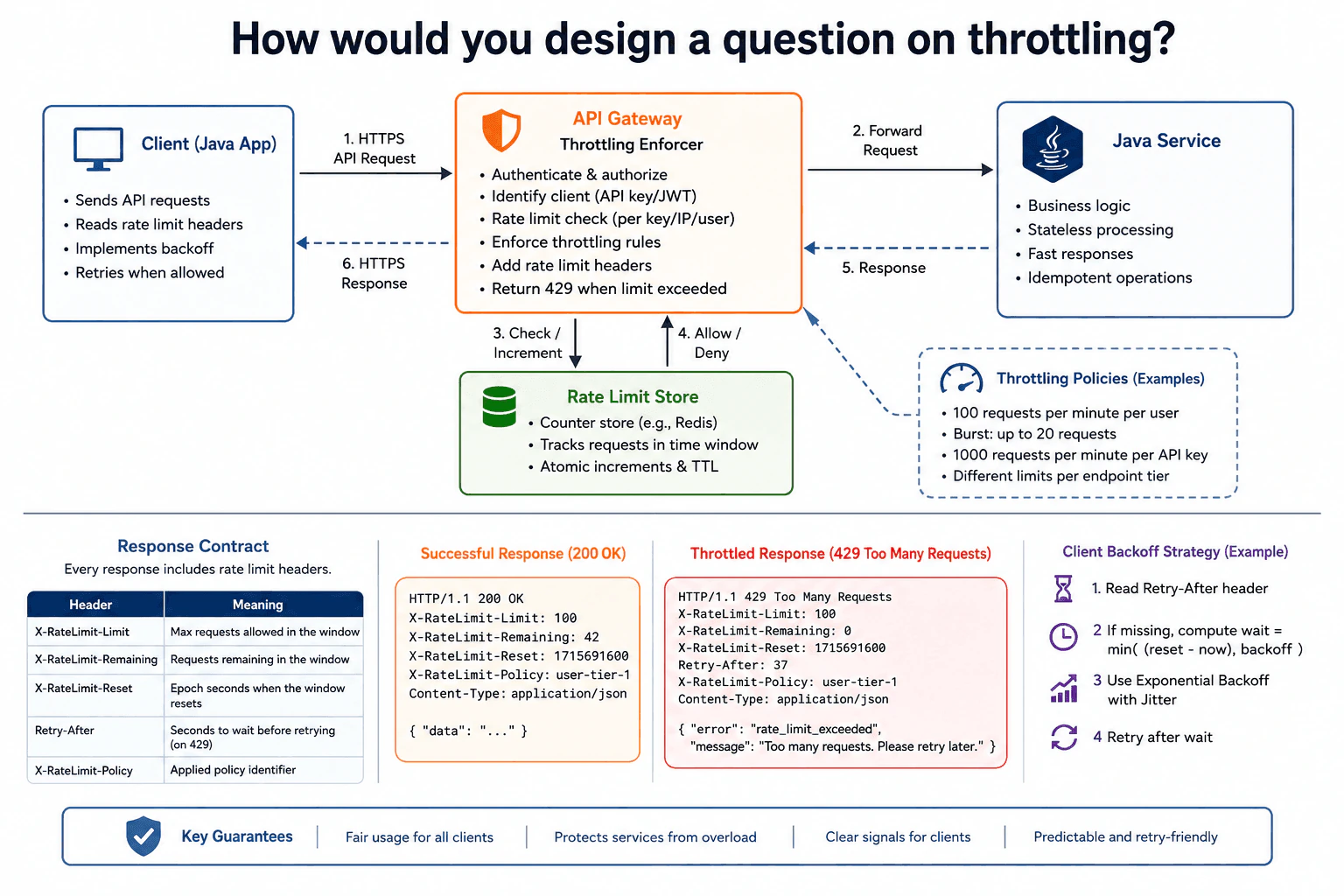
At a high level, I would design throttling so the gateway protects the service and tells clients exactly when to slow down. The Java client sends HTTPS requests to an API Gateway, which checks the client, applies per key, IP, or user limits, and either forwards the request to the Java service or returns 429 Too Many Requests. The gateway adds rate-limit headers so the client can back off in a clear way. The trade-off is stricter control at the edge, with a little extra state and coordination in the rate-limit store.
Detailed Explanation
This question asks how to stop one user from sending too many calls and slowing down everyone else. We need a clear rule for when to allow a call and when to ask the client to wait. The main challenge is giving a simple and fair answer so the client knows exactly when to try again. I will explain the design step by step using the attached diagram. It shows where the check happens, how the limit is tracked, what comes back, and how the client backs off and retries.
Useful Questions to Ask the Interviewer
Should the limit be per user, per API key, per IP address, or per endpoint?
Do we want only Retry-After, or also rate-limit headers like X-RateLimit-Remaining and X-RateLimit-Reset?
How to Explain It in an Interview
1. Start with the goal and boundary
At a high level, my goal is to protect the service from too many requests while giving clients a clear signal to wait. I would keep the Java application simple and put throttling at the API Gateway. That matches the diagram, where the client sends HTTPS requests to the gateway first. The gateway is the control point. It decides whether the request is allowed, and it adds the rate-limit information that clients need to back off correctly.
2. Explain how the gateway enforces throttling
The gateway is the throttling enforcer. It authenticates and authorizes the caller, identifies the client with an API key, JWT, user, or IP, and then checks the current limit. The diagram shows the gateway applying rules like per key, per IP, and per user. It also shows example policies such as 100 requests per minute per user and 1000 requests per minute per API key. If the request is allowed, the gateway forwards it. If the limit is exceeded, it returns 429 Too Many Requests.
3. Describe the rate-limit store and policy data
The gateway needs shared state to count requests correctly. That is why the diagram includes a Rate Limit Store, shown as a counter store such as Redis. It tracks requests in a time window and supports atomic increments and TTL, which means the count update happens safely and the old counter expires automatically. The store receives the check and increment step, then returns allow or deny to the gateway. This keeps the decision fast and consistent across replicas.
4. Walk through the request and response path
The main request path is client to gateway to Java service. The Java service stays stateless and handles business logic only. It does not own throttling. The response flows back the same way, from the service to the gateway and then to the client. On success, the diagram shows HTTP/1.1 200 OK. On throttling, it shows HTTP/1.1 429 Too Many Requests with a JSON body like error rate_limit_exceeded and a message telling the client to retry later. That makes the failure easy to understand.
5. Explain how the client knows when to back off
The client reads the rate-limit headers in every response. The diagram shows X-RateLimit-Limit, X-RateLimit-Remaining, X-RateLimit-Reset, and X-RateLimit-Policy. For a throttled response, it also shows Retry-After. The client should read Retry-After first. If that header is missing, it can wait for the smaller of the reset time and its own backoff delay, then add jitter. Jitter means a small random delay. That helps many clients avoid retrying at the same moment.
6. Close with guarantees and trade-offs
The design gives fair usage for all clients, protects the service from overload, and gives clear signals for retries. The trade-off is that the gateway and rate-limit store add more moving parts, and the system must keep the counter state correct across instances. I accept that cost because it gives predictable throttling behavior and a clean contract for clients. The key point is simple: the gateway decides, the store counts, the service stays focused on business logic, and the client backs off using the returned headers.
Practical Complexity & Trade-offs
The benefit is that the gateway can stop overload before it reaches the Java service. The client also gets a clear contract, because the response includes headers such as Retry-After and the X-RateLimit fields. The downside is that we need shared counter state, so the rate-limit store must be fast and reliable. This is safer than letting every service instance make its own guess, but it adds coordination. We accept that because it keeps throttling consistent across replicas. The design is also easy for clients to use, since they can back off with simple retry logic instead of guessing when to retry.
Why Interviewers Ask This
Interviewers ask this to see if I can design a clear contract for overload control, not just name a pattern. They want to know whether I can separate the gateway, the rate-limit store, and the Java service, and whether I understand who owns the throttle decision. They also check if I can explain client behavior, status codes, headers, and retry timing in simple words. The bigger signal is judgment: I should protect the service, keep the API easy to use, and explain the trade-off between strict control and extra state.
Interviewer may ask next
How would you change the design if you needed a small burst allowance but the same long-term limit?
If we wanted a stricter burst rule, I would keep the same gateway, store, headers, and client retry flow, but I would change the policy values. The affected part is the throttling policy that the gateway checks before forwarding a request. For example, we could keep the long-term limit at 100 requests per minute per user, but add a smaller burst bucket such as 20 quick requests. That still protects correctness because the gateway and rate-limit store continue to make the allow-or-deny decision before the Java service runs. Security also stays the same, because the gateway still identifies the client with the same API key, JWT, user, or IP. The downside is that burst control makes the policy harder to tune. If the burst is too small, good users may feel blocked even when the service is healthy. If it is too large, overload protection becomes weaker. So the trade-off is smoother traffic versus more policy tuning.
What would you do if some clients ignored Retry-After and retried too early?
If the client ignored Retry-After, I would still keep the same server design, but I would make the response contract more explicit. The affected parts are the 429 response and the client backoff logic. The gateway would continue to return X-RateLimit-Limit, X-RateLimit-Remaining, X-RateLimit-Reset, X-RateLimit-Policy, and Retry-After when the limit is exceeded. The client should first trust Retry-After. If it is missing, it can use the reset time and then add exponential backoff with jitter. That keeps correctness because the server still makes the throttle decision, and the client still has enough information to wait safely. The downside is that some clients may still retry too early if they do not follow the contract. That can create extra load and more 429 responses. So the trade-off is that we can make the guidance very clear, but we cannot force every client to behave well unless we also enforce retry behavior in shared libraries or SDKs.
19. How would you design a shared pointer abstraction?API DesignMediumNvidia
i Question Details
Design the interface and ownership semantics for a shared-pointer style abstraction.
Short Interview Answer (30-60 seconds)
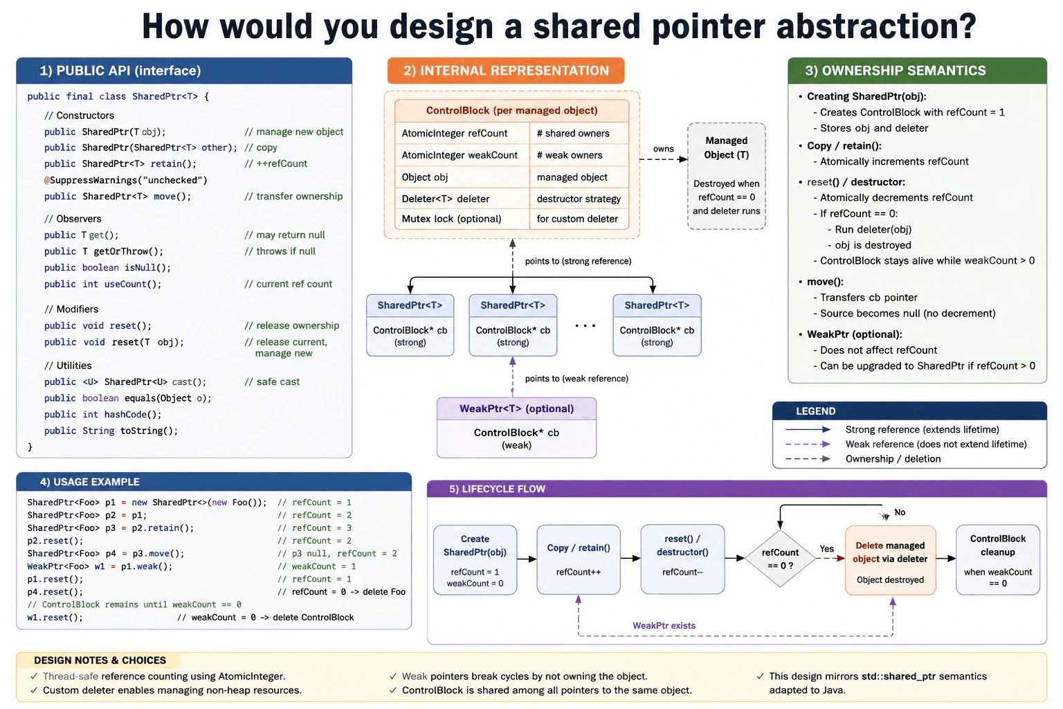
At a high level, I would make the design about safe shared ownership of one object. A SharedPtr<T> keeps the object alive, a WeakPtr<T> watches it without owning it, and a shared ControlBlock tracks refCount and weakCount with atomic counters. The main flow is create, copy with retain(), move, reset, and optional weak upgrade. The key reliability choice is thread-safe reference counting. The trade-off is a little extra overhead for each copy, but much clearer lifetime rules.
Detailed Explanation
This question asks how to build a small wrapper around one object so many parts of a program can share it safely. The goal is to keep one live object, know who still uses it, and free it at the right time. The main challenge is lifetime control. One handle should own the object. Another should only observe it. I will follow the diagram closely and explain the exact public SharedPtr<T> API, the shared ControlBlock, and the rules for WeakPtr.
Useful Questions to Ask the Interviewer
Do you want the weak handle to support upgrade only, or also explicit lock and reset helpers?
Should the design support custom deleters for files or native handles?
Do you want thread-safe reference counts from day one?
How to Explain It in an Interview
1. Public API
I would start with the public SharedPtr<T> class shown in the diagram. It has a constructor for a new object, a copy constructor, retain(), move(), get(), getOrThrow(), isNull(), useCount(), reset(), reset(T obj), cast(), equals(), hashCode(), and toString(). The reason for this API is simple. It gives normal Java-style access, but it still makes ownership very clear. get() may return null, while getOrThrow() is the strict option.
2. Internal representation
Under the API, I would store one shared ControlBlock per managed object. The diagram shows AtomicInteger refCount for strong owners, AtomicInteger weakCount for weak observers, the actual Object obj, a Deleter<T> strategy, and an optional Mutex lock for a custom deleter. This block is the source of truth. Every SharedPtr copy points to the same block, so the counts stay in one place. That makes the ownership rules easy to explain and easy to audit.
3. Ownership semantics
Creation with new SharedPtr<T>(obj) makes a control block with refCount = 1. Copying or calling retain() increments refCount atomically. move() transfers the control-block pointer and leaves the source null, so there is no extra decrement. reset() drops one strong owner, and reset(T obj) first releases the current object and then starts managing the new one. The object stays alive while refCount > 0. When refCount reaches zero, the deleter runs and destroys the managed object.
4. Weak ownership and lifecycle
The diagram also shows an optional WeakPtr<T>. A weak pointer does not change refCount. It only watches the same control block. That is useful when two objects should not keep each other alive forever. If the weak side is upgraded and refCount > 0, it can become a new SharedPtr. The lifecycle flow is create, copy, reset, destroy the managed object when strong count reaches zero, and clean up the control block when weakCount also reaches zero.
5. Trade-offs and why this design works
The main benefit is predictable lifetime with shared ownership. The downside is overhead. Every copy or reset touches atomic counters, so this is slower than raw pointers. The optional custom deleter adds flexibility for non-heap resources, but it also adds complexity. I would accept that trade-off because the design is safer, easier to reason about, and matches the diagram’s ownership model. It also keeps the public API small while still covering common Java needs like comparison, hashing, string output, and safe casts.
Practical Complexity & Trade-offs
This design is easy to explain because all ownership state lives in one control block. The strong count tells us how many SharedPtr handles are still alive. The weak count tells us whether any observers still need the block. That separation makes destruction rules clear and keeps the public API small. The benefit is safer sharing, simple retain() and reset() behavior, and a clean way to support WeakPtr and custom deleters. The downside is extra memory, atomic updates on every copy, and a little more code around upgrade and cleanup. We accept that cost because it avoids dangling pointers, supports shared ownership, and makes lifetime rules explicit.
Why Interviewers Ask This
Interviewers ask this to see whether you understand object lifetime, shared ownership, and safe cleanup. They also want to know if you can separate strong ownership from weak observation, and if you can explain when the managed object and control block should be destroyed. Good answers show clear API design, correct reference counting, and simple trade-off thinking. A strong answer also shows that you can explain thread safety and custom deletion without making the design sound more complex than it is.
Interviewer may ask next
How would you make the shared pointer safe when two threads copy and reset it at the same time?
Yes, I would make the reference counts atomic so the design stays correct when two threads copy or reset the same handle at the same time. That change affects the ControlBlock, not the public API. refCount and weakCount remain the source of truth, and retain(), copy construction, move(), and reset() still follow the same ownership rules. The managed object is still deleted only when refCount reaches zero, and the control block is still cleaned up only after weakCount also reaches zero. If the diagram’s optional Mutex lock is needed for a custom deleter, I would keep that lock very small and only use it around the deleter path, not for normal reads. The main downside is overhead. Atomic operations are slower than plain integers, and that cost shows up on every ownership change. I would still keep this design because it gives predictable lifetime behavior and avoids race conditions around destruction.
How would you support weak references that can be upgraded only while the object is still alive?
Yes, I would keep the weak handle as a non-owning observer and let it upgrade only when refCount > 0. That change affects the weak path, not the strong path. The weak side still points to the same ControlBlock, but it does not change the strong count by itself. If the strong count is already zero, the upgrade must fail and return an empty shared handle, because the managed object has already been deleted. That keeps the ownership rules safe and easy to reason about. It also matches the lifecycle flow in the diagram, where the object is destroyed first and the control block is released later. The main downside is that callers must handle an empty result, so the code is a little more explicit. I would accept that because it keeps weak references useful without letting them accidentally keep dead objects alive.
20. How would you design a ternary tree using inheritance and polymorphism?API DesignMediumNvidia
i Question Details
Design the object model for a ternary tree and explain how inheritance and polymorphism would fit the design.
Short Interview Answer (30-60 seconds)
At a high level, I would make one abstract ternary node that holds the common links: left, middle, and right. Then I would add concrete node types like data, sum, and decision nodes for special behavior. The key idea is that tree code works on the base type, while the actual method comes from the real node at runtime. The main trade-off is a little more class structure, but the design stays clean and easy to extend.
Detailed Explanation
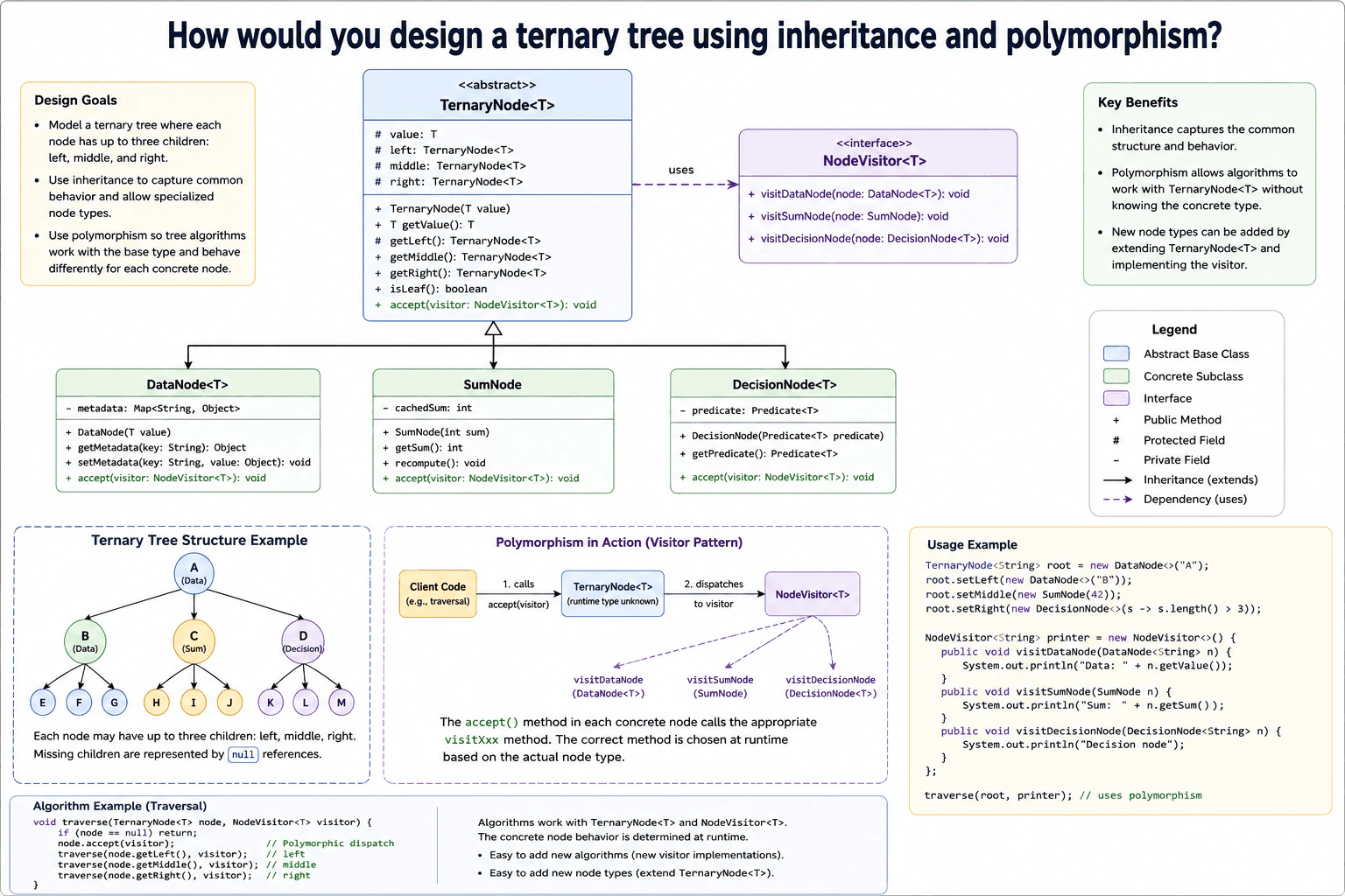
This question asks how to organize a tree-shaped structure where each item can have three children. The goal is to share the common parts, but still let each kind of item keep its own details. The tricky part is making one tree design work for different node shapes without rewriting the tree logic every time. I will follow the diagram step by step: first the shared base node, then the three special node types, and then the way one action can run across all of them.
Useful Questions to Ask the Interviewer
Do we expect only these three node types, or could more node types appear later?
Should the tree support extra operations, such as printing or validation?
Do we need the decision node to use a rule object, as shown in the diagram?
How to Explain It in an Interview
1. Start with the shared base node
I would begin with one abstract TernaryNode<T> class. It holds the common state for every node. That state is value, left, middle, and right. It also gives shared methods like getValue(), getLeft(), getMiddle(), getRight(), isLeaf(), and accept(visitor). This is the part that keeps the tree shape consistent. Every node in the tree can use the same basic links, so the rest of the code does not need to know the exact node type.
2. Add the concrete node types
Next, I would add the three concrete classes from the diagram. DataNode<T> stores extra metadata in a map. SumNode stores a cached sum and can recompute it. DecisionNode<T> stores a Predicate<T>, which is just a rule that returns true or false. These classes extend the base node, so they inherit the ternary tree structure. They only add the data and behavior that belong to their own job.
3. Use polymorphism through accept(visitor)
The main polymorphism idea is the accept(visitor) method. The client code works with TernaryNode<T>, not with each child class directly. At runtime, the real object decides which visitor method to call. So a DataNode calls visitDataNode(), a SumNode calls visitSumNode(), and a DecisionNode calls visitDecisionNode(). This is useful because the tree traversal does not need if checks for every node type.
4. Traverse the tree in the same order every time
The traversal logic in the diagram goes left, then middle, then right. That is a simple recursive walk. If a child is missing, the reference is null, so the walk stops there. The example tree shows that the tree can be uneven. That is fine. A ternary tree does not need every node to have three children. The important part is that the same base type and the same traversal logic work for every node.
5. Explain the trade-off
The benefit is that inheritance captures the shared structure, and polymorphism keeps the algorithms simple. I can add new operations by writing a new visitor. The downside is that I now have more classes, and adding a brand-new node type means updating the visitor interface too. I would accept that trade-off because it keeps the tree design clear, and it separates node data from tree behavior.
Why Interviewers Ask This
Interviewers ask this to see if I can model shared structure cleanly and still keep behavior flexible. They want to know if I understand when inheritance helps, when polymorphism helps, and how to separate node data from tree operations. They also check whether I can explain runtime dispatch, null children, and the trade-off between easy new operations and extra class complexity. In short, they are testing design judgment, not memorized patterns.
Interviewer may ask next
What if the tree needed a fourth child instead of three?
I would change the base node to hold a fourth child pointer and update the traversal order to include it. The affected parts are the abstract TernaryNode<T> class, every concrete node constructor, and the visitor-based traversal logic. The design still works, because the shared base type still owns the common structure. The correctness rule is simple: every child position must be visited in the same order everywhere. The downside is that this is no longer a ternary tree, so the name and the example would need to change. Also, any code that assumes exactly three children would need to be updated. I would make that change only if the domain really needs four fixed child slots.
What if we want a new operation like pretty printing without changing the node classes?
I would add a new visitor implementation for that operation. The node classes would stay the same, because they already expose accept(visitor). The new visitor could walk the tree and print each node in a readable format. This keeps the node model stable and puts the new behavior in one place. Correctness stays strong because the runtime type still selects the right visit...() method for each node. The main downside is that the visitor interface grows over time, and every visitor may need an update when a new node type is added later. Still, for new operations, this is the cleanest part of the design, because I do not have to touch DataNode, SumNode, or DecisionNode.
More questions load as you scroll
Disclaimer: This interview guide is for educational and informational purposes only. It is designed to help readers prepare, but it does not guarantee any interview result, hiring decision, offer, or outcome. Interview questions, hiring criteria, and preferred answers can vary by employer, interviewer, industry, location, and time. All answers, examples, and explanations in this guide are suggested examples for interview preparation, not definitive answers or instructions for professional practice. They are based on research and judgment, are provided without warranties of any kind, and should be adapted to the question, role, and applicable laws and professional requirements. Diagrams are simplified illustrations intended to highlight the main concepts and their relationships; actual situations, systems, and practices may be more complex. Alternative approaches may be equally valid or better suited to a particular question, context, or interviewer. To the fullest extent permitted by applicable law, the contributors and publisher are not liable for decisions made, actions taken, or losses incurred based on this guide.
State Laws and Professional Responsibilities: Laws and requirements governing an occupation vary by state and jurisdiction. You are responsible for checking the current laws, licensing requirements, and scope-of-practice rules that apply to your location and role, and for ensuring that your answers and actions comply with them. Adapt examples in this guide to those requirements. This guide is not legal advice.
Company Notice: This guide is an independent educational resource and is not affiliated with, endorsed by, sponsored by, or approved by the company named in this guide. Company names identify reported interview experiences or the employer context of clearly labeled original practice exercises. Interview practices can change without notice, and inclusion of company-specific content does not mean these questions are official, complete, or guaranteed to be asked. To the fullest extent permitted by law, the author, contributors, and publisher are not responsible for outcomes related to use of this material.
Content Accuracy and Verification: To the fullest extent permitted by applicable law, we do not represent or warrant that interview guides, questions, answers, examples, or diagrams are accurate, complete, current, error-free, or suitable for any particular purpose. You are responsible for independently reviewing and verifying the information before relying on it.