This interview guide is for educational and informational purposes only. It is designed to help readers prepare, but it does not guarantee any interview result, hiring decision, offer, or outcome. Interview questions, hiring criteria, and preferred answers can vary by employer, interviewer, industry, location, and time. All answers, examples, and explanations in this guide are suggested examples for interview preparation, not definitive answers or instructions for professional practice. They are based on research and judgment, are provided without warranties of any kind, and should be adapted to the question, role, and applicable laws and professional requirements. Diagrams are simplified illustrations intended to highlight the main concepts and their relationships; actual situations, systems, and practices may be more complex. Alternative approaches may be equally valid or better suited to a particular question, context, or interviewer. To the fullest extent permitted by applicable law, the contributors and publisher are not liable for decisions made, actions taken, or losses incurred based on this guide.
State Laws and Professional Responsibilities
Laws and requirements governing an occupation vary by state and jurisdiction. You are responsible for checking the current laws, licensing requirements, and scope-of-practice rules that apply to your location and role, and for ensuring that your answers and actions comply with them. Adapt examples in this guide to those requirements. This guide is not legal advice.
Identity, Image, and Privacy Notice
To respect individual privacy, some names, profile photographs, avatars, biographical details, and other identifying information displayed in this guide may be replaced with pseudonyms, licensed stock images, illustrative avatars, composite images, or representative descriptions. Unless a person is expressly identified as an actual contributor, a displayed name, image, or profile should not be understood as depicting or identifying a specific candidate, interviewer, employee, or other real individual. These representations are provided for editorial and illustrative purposes only and do not imply endorsement, employment, participation, or affiliation with this guide or any company mentioned in it. Any resemblance to an actual person is coincidental.
Company Notice
This guide is an independent educational resource and is not affiliated with, endorsed by, sponsored by, or approved by the company named in this guide. Company names identify reported interview experiences or the employer context of clearly labeled original practice exercises. Interview practices can change without notice, and inclusion of company-specific content does not mean these questions are official, complete, or guaranteed to be asked. To the fullest extent permitted by law, the author, contributors, and publisher are not responsible for outcomes related to use of this material.
Content Accuracy and Verification
To the fullest extent permitted by applicable law, we do not represent or warrant that interview guides, questions, answers, examples, or diagrams are accurate, complete, current, error-free, or suitable for any particular purpose. You are responsible for independently reviewing and verifying the information before relying on it.
Questions or comments?
Contact us for general questions, or share feedback, technical corrections, and comments with the community.
21. How would you assess the effect of uncertain envelope data on an HVAC load calculation?Heating And Cooling Load CalculationsHard
i Question Details
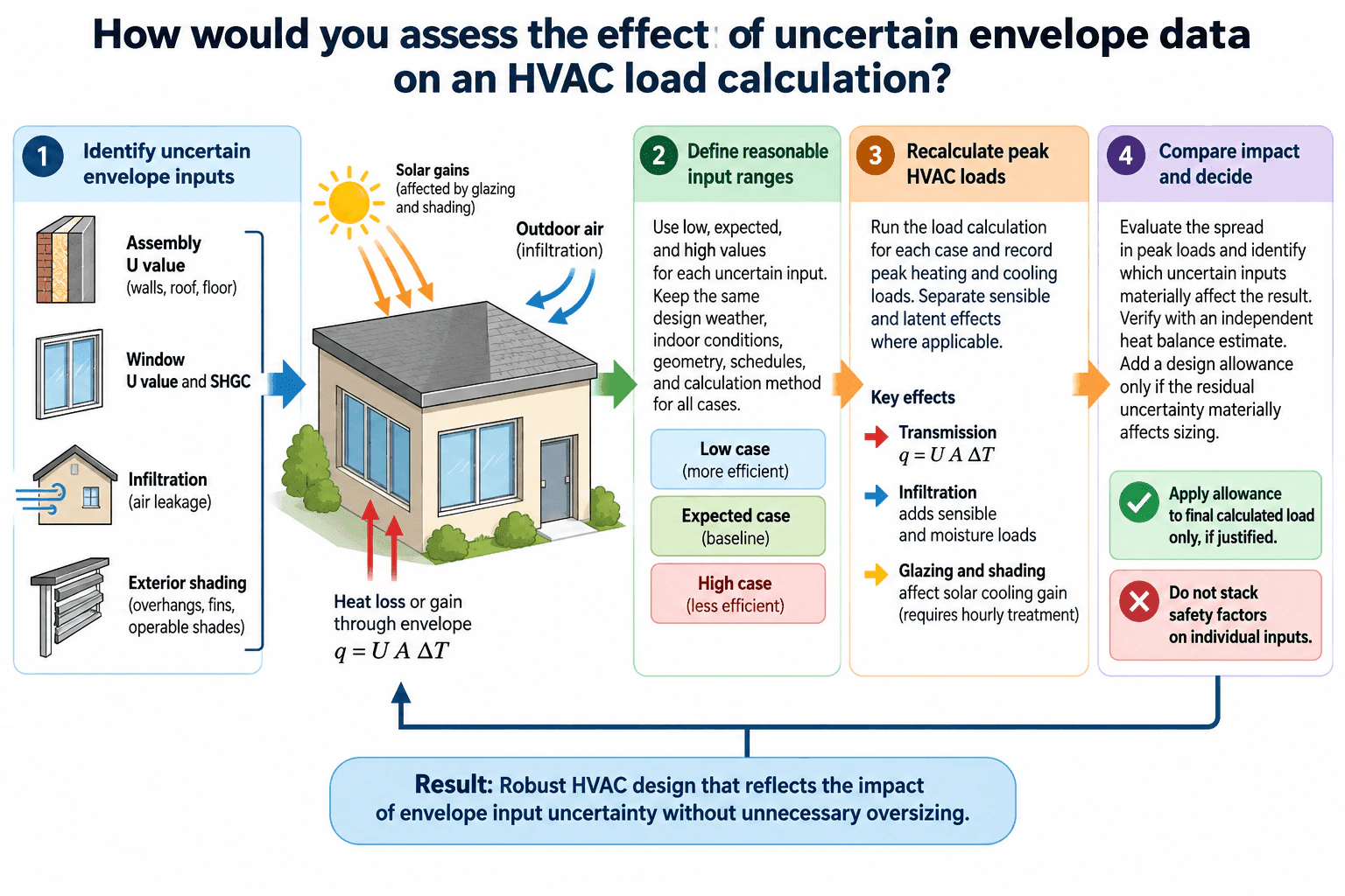
Explain how to identify uncertain U-values, glazing properties, infiltration, and shading assumptions, test reasonable sensitivity cases, and decide whether any design allowance is justified.
Short Interview Answer (30-60 seconds)
I would first identify the uncertain envelope inputs, such as assembly U values, window U value and SHGC, infiltration, and exterior shading. I would assign reasonable low, expected, and high values to those inputs, then rerun the peak heating and cooling load calculation while keeping design weather, indoor conditions, geometry, schedules, and the calculation method unchanged. I would compare the resulting peak loads, separate sensible and latent effects where applicable, and verify the result with an independent heat balance estimate. I would add a design allowance only when the remaining uncertainty materially affects the sizing load, rather than stacking safety factors on individual inputs.
Detailed Explanation
Uncertain envelope data should be treated as an input sensitivity problem, not as a reason to apply a blanket oversizing factor. The objective is to determine which uncertain assumptions materially change the peak heating or cooling load and whether the remaining uncertainty justifies an allowance.
Useful Questions to Ask the Interviewer
Which envelope inputs are uncertain, and what information is available to define reasonable ranges for them?
Are we assessing a room, zone, or coincident building peak, and what design weather and indoor conditions should remain fixed?
Is the objective only to understand sensitivity, or also to determine a final sizing input from the sensitivity results?
How to Explain It in an Interview
I would begin by separating known inputs from uncertain inputs. Typical uncertain envelope inputs include wall, roof, and floor U values, window U value and SHGC, infiltration, and exterior shading. I would document an expected value plus defensible lower and upper values for each uncertain input instead of adding a safety factor immediately.
For transmission, the basic relationship is q = U A ΔT, where q is heat transfer rate, U is overall heat transfer coefficient, A is surface area, and ΔT is the indoor to outdoor temperature difference. If area and temperature difference are unchanged, a higher U value increases transmission heat gain or heat loss. Window SHGC and shading affect solar cooling gain. Infiltration can add sensible load and, when outdoor air contains more moisture than indoor air, latent load.
I would then create low, expected, and high sensitivity cases. To make the comparison meaningful, I would keep design weather, indoor conditions, geometry, schedules, and the calculation method the same while varying the uncertain envelope assumptions. Where shading changes with solar position and time, I would use the appropriate hourly treatment rather than treating shading as a single fixed conductive effect.
For each case, I would record peak heating and cooling loads and separate sensible and latent effects where applicable. I would compare the spread between cases and identify which uncertain inputs materially affect the result. I would also make sure I am comparing the same room, zone, or coincident building peak definition in every case instead of adding noncoincident peaks.
Finally, I would validate the software result with an independent heat balance estimate and review units, design conditions, schedules, and input assumptions. If the sensitivity spread is small, I would use the calculated load without an arbitrary allowance. If credible unresolved uncertainty materially changes the sizing load, I would document that uncertainty and apply a justified allowance to the final calculated load. I would not stack separate safety factors on individual uncertain inputs because that can lead to unnecessary oversizing.
Why Interviewers Ask This
Interviewers want to see whether the candidate can identify uncertain load inputs, quantify their effect through controlled sensitivity cases, distinguish material uncertainty from minor variation, validate the result independently, and avoid arbitrary oversizing.
Common interview mistakes
Common mistakes include applying arbitrary oversizing margins before testing sensitivity, changing several unrelated assumptions at the same time without tracking their effect, treating uncertain shading or SHGC as if they affect only conductive heat transfer, ignoring latent infiltration load, using different design conditions between cases, adding noncoincident room or zone peaks, and accepting software output without an independent reasonableness check.
Interview tip
Explain the process as controlled sensitivity analysis: identify uncertainty, define defensible ranges, hold the rest of the calculation constant, compare peak loads, validate independently, and apply an allowance only when the remaining uncertainty materially affects sizing. This demonstrates engineering judgment rather than automatic oversizing.
Interviewer may ask next
How would you validate the sensitivity study before using its result for sizing?
I would check the U values, areas, SHGC assumptions, infiltration inputs, shading assumptions, schedules, indoor conditions, and design weather for consistent units and assumptions. I would then compare the software result with an independent heat balance estimate, including a transmission check using q = U A ΔT and a reasonableness review of the expected direction and approximate magnitude of solar and infiltration effects. I would also confirm that the same room, zone, or coincident building peak definition is used across all sensitivity cases.
What would you do if the high sensitivity case produces a much larger load than the expected case?
I would identify which uncertain input causes the increase and determine whether that value is genuinely plausible. I would seek better evidence, such as envelope documentation, glazing data, field information, or infiltration measurements when available. If the uncertainty cannot be resolved and the credible range materially affects the final sizing load, I would document the sensitivity and apply a justified allowance to the final calculated load. I would not automatically use the most conservative value for every uncertain input or stack multiple safety factors.
22. How would you separate process loads from normal comfort-conditioning loads in a specialized space?Heating And Cooling Load CalculationsHard
i Question Details
Identify which heat and moisture gains are tied to equipment or processes, determine their operating schedules and diversity, and explain why they must not be hidden inside generic occupancy assumptions.
Short Interview Answer (30-60 seconds)
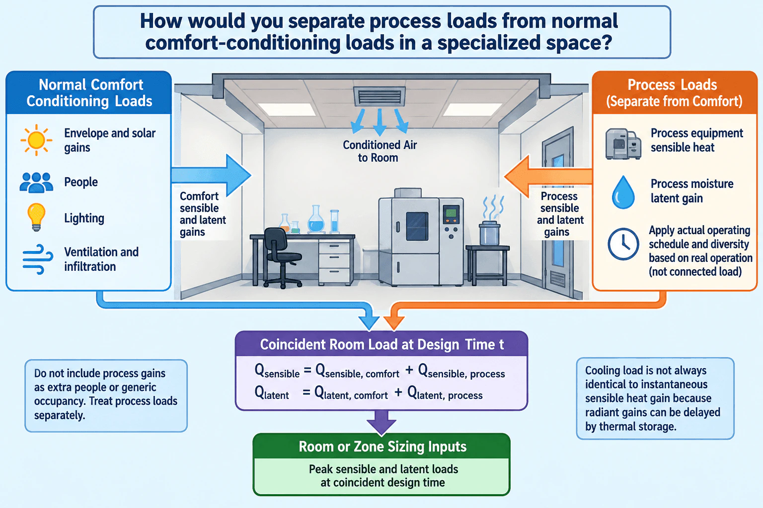
I would calculate comfort loads and process loads as separate load streams. Comfort loads include envelope and solar gains, people, lighting, ventilation, and infiltration. Process loads include sensible heat and moisture generated by specialized equipment or activities. For each process, I would use its actual operating schedule and realistic diversity rather than connected load. I would then combine the coincident sensible and latent contributions at each design time to determine the room or zone sizing inputs.
Detailed Explanation
The key is to keep process gains visible as their own load category instead of hiding them inside people or a generic equipment allowance. That preserves the source, schedule, sensible versus latent split, and peak timing that determine the actual room load.
Useful Questions to Ask the Interviewer
What specialized equipment or processes operate in the space, and which of them release sensible heat or moisture into the room?
What are the actual operating schedules, duty cycles, and expected diversity of those processes?
Are we evaluating a room, a zone, or a coincident block load, and what design conditions should be used?
How to Explain It in an Interview
Calculation Basis
I would define the room boundary and design conditions first, then create two separate load streams.
Comfort loads include envelope and solar gains, people, lighting, ventilation, and infiltration. Depending on the source, they can contribute sensible load, latent load, or both.
Process loads include sensible heat released by specialized equipment and latent load caused by process moisture. I would not represent these gains as extra occupants because that hides their physical source and operating behavior.
Load Inputs
For each process source, I would identify its sensible heat contribution, latent moisture contribution, actual operating schedule, duty cycle, and diversity. Connected equipment capacity is not automatically the room load. The important input is the load actually released into the conditioned space while the process operates.
I would keep the comfort schedules separate because occupants, lighting, ventilation, solar gain, and process equipment can peak at different times.
Sizing Reasoning
At each design time t, I would combine only the loads that are actually coincident:
I would evaluate those totals through the relevant design period and use the coincident peak sensible and latent loads as room or zone sizing inputs. I would not simply add separate noncoincident peaks.
I would also distinguish heat gain from cooling load. Some sensible radiant gains can be stored temporarily in room surfaces, so the resulting cooling load can occur later than the original heat gain.
Finally, I would validate units, schedules, sensible and latent splits, outdoor design conditions, and peak timing. I would compare the software result with an independent heat balance estimate. If the process schedule, diversity, or moisture generation changes, I would recalculate the coincident peak rather than applying an arbitrary oversizing margin.
Why Interviewers Ask This
This evaluates whether the candidate can identify the true sources of sensible and latent load, apply realistic operating schedules and diversity, preserve peak timing, and avoid hiding process gains inside generic occupancy assumptions that can distort room or zone sizing.
Common interview mistakes
Common mistakes include treating process gains as generic occupancy, using connected equipment load without applying the actual operating schedule and diversity, combining sensible and latent gains too early, adding noncoincident peaks, ignoring process moisture, and assuming instantaneous sensible heat gain is always equal to the cooling load at the same time.
Interview tip
Structure the answer around separation, timing, and coincidence. Name the comfort sources, name the process sources, explain how actual schedules and diversity are applied, then show that the final room or zone sizing inputs come from coincident sensible and latent peaks rather than a simple sum of independent maximum values.
Interviewer may ask next
How would you validate the process load assumptions if equipment data were incomplete?
I would separate known values from assumptions and identify the missing heat and moisture information. I would review available manufacturer data, process descriptions, operating schedules, and measured electrical or thermal information where appropriate. I would create an independent heat balance estimate, compare it with the calculated result, and test reasonable operating cases. I would not hide uncertain process gains inside occupancy or add an arbitrary sizing margin.
What changes if the process equipment operates intermittently and its peak does not coincide with the comfort load peak?
I would model the actual process schedule and evaluate the combined room load over time. The design load should reflect the largest coincident sensible and latent requirement, not the sum of independent maximum values. If the process peak occurs when solar, occupancy, or other comfort loads are lower, the coincident room peak can be smaller than the sum of those separate peaks.
23. What is static pressure, and why does it matter when selecting an HVAC fan?Air Distribution And Duct DesignEasy
i Question Details
Define static pressure in an air-distribution system and identify common resistances such as filters, coils, ducts, fittings, and terminals that the fan must overcome.
Short Interview Answer (30-60 seconds)
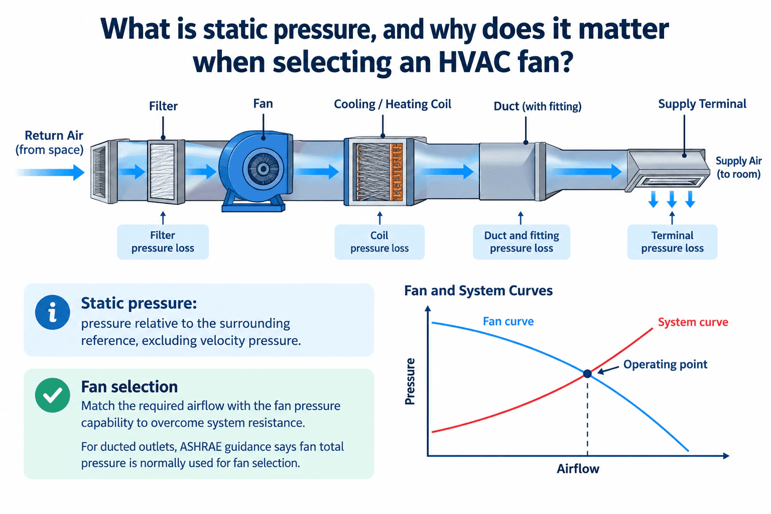
Static pressure is the air pressure relative to a chosen reference, excluding velocity pressure. In an HVAC distribution system, filters, coils, ducts, fittings, and terminals create resistance as air moves through them. The fan must provide enough pressure capability at the required airflow to overcome that system resistance. The actual operating point is where the fan curve intersects the system curve. For a fan with a ducted outlet, fan total pressure is normally the appropriate basis for fan selection because it accounts for both static and velocity pressure effects.
Detailed Explanation
Static pressure is the pressure of the air relative to a selected reference without including velocity pressure. In a duct system, it can be positive or negative relative to the surrounding space depending on where it is measured. Filters, heating or cooling coils, straight ducts, fittings, and supply terminals all resist airflow and contribute to the pressure requirement that the fan must overcome.
Useful Questions to Ask the Interviewer
What airflow must the system deliver at the design condition?
Which filters, coils, ducts, fittings, and terminals are included in the pressure path?
Is the fan outlet ducted, and what pressure data are available for the system components?
How to Explain It in an Interview
I would start with the required airflow and trace the complete air path. In this system, return air passes through the filter, then the fan, then the heating or cooling coil, the duct and fitting, and finally the supply terminal. Each passive component adds resistance that contributes to the required fan pressure.
Static pressure is different from velocity pressure. Velocity pressure represents the kinetic energy associated with air speed. Total pressure combines static pressure and velocity pressure. That distinction matters when duct area or velocity changes and when fan performance is evaluated.
For fan selection, I would determine the pressure requirement along the critical air path at the design airflow. Filter and coil losses should come from applicable equipment data at that airflow. Duct and fitting losses come from the duct pressure loss calculation, and the terminal has its own pressure requirement at the design flow.
The fan curve shows the pressure a fan can produce at different airflow rates. The system curve shows how much pressure the system requires as airflow changes. Their intersection is the operating point. The selected fan should place that operating point at or near the required airflow and pressure condition.
For a fan with a ducted outlet, I would normally use fan total pressure as the fan selection basis rather than treating static pressure alone as the complete fan pressure requirement. Static pressure measurements are still important for evaluating distribution performance, balancing, leakage, and component pressure drops.
Before finalizing the selection, I would verify the critical path, expected filter condition, coil data, duct and fitting losses, terminal requirements, and fan performance data. I would also check noise, vibration, duct leakage, and room air delivery.
Why Interviewers Ask This
Interviewers want to confirm that the candidate understands air system resistance, can distinguish static pressure from velocity pressure and total pressure, and can connect filters, coils, ducts, fittings, and terminals to the pressure capability required from a fan.
Common interview mistakes
Common mistakes include treating static pressure as the same as total pressure, selecting a fan from airflow alone, ignoring filters, coils, fittings, or terminals, using pressure loss data from the wrong airflow condition, overlooking the critical air path, and assuming that a fan will deliver its rated airflow regardless of system resistance.
Interview tip
Define static pressure first, then connect it directly to system resistance and fan selection. Trace the same airflow path shown in the diagram from return air through the filter, fan, coil, duct and fitting, and supply terminal. Finish by explaining that the fan and system curve intersection establishes the operating point.
Interviewer may ask next
How would you validate that the selected fan can overcome the actual system resistance?
I would confirm the required airflow, identify the critical air path, and verify the filter, coil, duct, fitting, and terminal pressure requirements at that airflow. I would compare the resulting system requirement with the fan performance data and confirm that the fan and system curves intersect at an acceptable operating point. During commissioning, measured airflow and pressure readings can be compared with the design assumptions.
What happens if the original filter is replaced by one with a higher pressure drop?
The system resistance increases. On the system curve, the pressure requirement is higher for a given airflow. With the same fan running at the same speed, the operating point generally moves to a lower airflow. I would check the new filter pressure drop against the fan curve and determine whether the fan still has enough pressure capability to maintain the required airflow without unacceptable noise, vibration, or energy use.
24. What is duct friction loss?Air Distribution And Duct DesignEasy
i Question Details
Define friction loss as pressure loss through ductwork and explain the influence of duct size, airflow, length, roughness, and fittings.
Short Interview Answer (30-60 seconds)
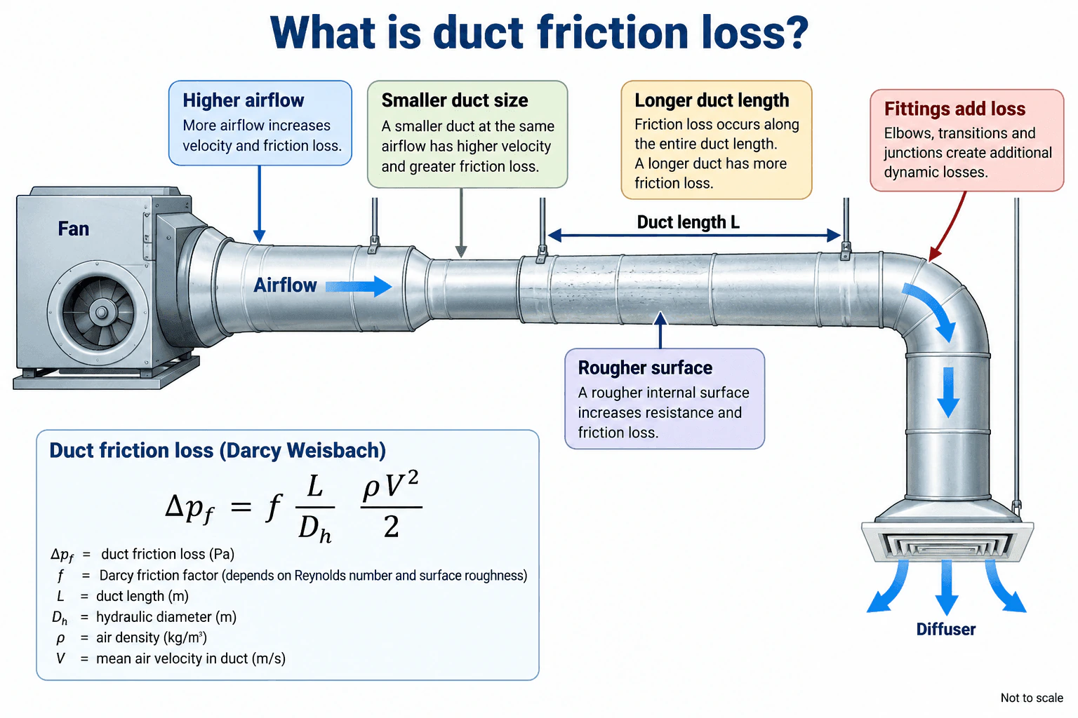
Duct friction loss is the pressure loss that occurs as moving air experiences resistance along the inside surface of a duct. Higher airflow through the same duct increases air velocity and usually increases friction loss. For the same airflow, a smaller duct has higher velocity and greater loss. Longer ducts accumulate more friction loss, and rougher internal surfaces can increase resistance. Elbows, transitions, and junctions add separate dynamic pressure losses. The fan must overcome the combined system resistance to deliver the required airflow to the diffuser.
Detailed Explanation
Duct friction loss is the reduction in air pressure caused by resistance between moving air and the internal duct surface. It occurs continuously along the duct length. In the illustrated air path, the fan moves air through the duct toward the diffuser, while airflow, duct size, duct length, surface roughness, and fittings all influence the pressure required to maintain that flow.
For straight duct, the Darcy Weisbach relationship can be written as Δp_f = f × (L ÷ D_h) × (ρV² ÷ 2). Here, Δp_f is straight duct friction pressure loss in Pa, f is the Darcy friction factor, L is duct length in m, D_h is hydraulic diameter in m, ρ is air density in kg/m³, and V is mean air velocity in m/s. The friction factor depends on Reynolds number and relative surface roughness.
Useful Questions to Ask the Interviewer
Should I explain only straight duct friction loss, or also include fitting losses when discussing total system pressure loss?
Should I assume airflow remains constant when comparing different duct sizes?
Would you like the explanation in SI units or another unit system?
How to Explain It in an Interview
Start with the physical idea: the fan supplies pressure to move air, and part of that pressure is consumed overcoming resistance as air travels through the duct.
Airflow and velocity: If more airflow passes through the same duct area, velocity increases. Because the Darcy Weisbach relationship includes V², straight duct friction loss generally rises strongly as velocity increases, although the friction factor also changes with Reynolds number and roughness.
Duct size: For the same airflow, a smaller duct has less cross sectional area, so velocity increases. A smaller hydraulic diameter also increases the L ÷ D_h term. Both effects increase straight duct friction loss.
Duct length: Friction acts along the duct surface, so a longer duct produces a greater total friction loss when the other conditions remain approximately unchanged.
Surface roughness: A rougher internal surface can increase the Darcy friction factor in turbulent flow, which increases friction loss.
Fittings: Elbows, transitions, and junctions disturb or redirect airflow and create additional dynamic pressure losses. These fitting losses are added to straight duct friction and other component losses when determining total system pressure requirements.
The practical conclusion is that duct pressure loss is not determined by airflow alone. An HVAC engineer considers the full air path from the fan through straight duct sections, fittings, and the diffuser. If total resistance is too high, the fan may not deliver the required airflow. Excessive velocity can also increase noise, so duct sizing balances pressure loss, airflow delivery, and acoustic performance.
Why Interviewers Ask This
Interviewers want to confirm that the candidate understands why air loses pressure while moving through ductwork and can explain how airflow, duct size, duct length, internal roughness, and fittings affect that loss. They also want the candidate to distinguish straight duct friction loss from the additional dynamic pressure losses created by fittings.
Common interview mistakes
Common mistakes include treating straight duct friction as the only pressure loss in the system, ignoring fitting losses, discussing duct size without considering its effect on air velocity, forgetting that friction loss accumulates with duct length, and assuming surface roughness has no effect on the friction factor. Another mistake is treating static pressure and total pressure as the same quantity or applying the straight duct Darcy Weisbach expression directly to fittings instead of accounting for their separate dynamic losses.
Interview tip
Give the definition first, then connect each influencing factor to the physical cause. Explain that higher airflow through the same duct increases velocity, smaller ducts increase velocity and reduce hydraulic diameter, longer ducts accumulate more friction, rough surfaces can increase the friction factor, and fittings add separate dynamic losses. Finish by connecting the combined resistance to the pressure the fan must provide to deliver the required airflow to the diffuser.
Interviewer may ask next
If two ducts have the same size, airflow, roughness, and air properties but one is twice as long, what happens to the straight duct friction loss?
If the friction factor, hydraulic diameter, air density, and velocity remain approximately unchanged, the Darcy Weisbach relationship shows that straight duct friction loss is proportional to length. Doubling the duct length therefore approximately doubles the straight duct friction pressure loss.
What happens if the same airflow must pass through a smaller duct?
The air velocity increases because the same volumetric airflow passes through a smaller cross sectional area. The hydraulic diameter also decreases. Both effects increase straight duct friction loss, so the fan must overcome greater resistance. The higher velocity can also increase airflow noise.
25. What is duct aspect ratio?Air Distribution And Duct DesignEasy
Short Interview Answer (30-60 seconds)
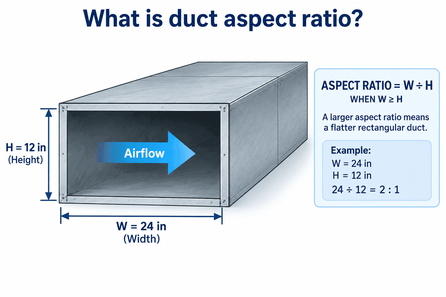
Duct aspect ratio describes the proportion between the two side dimensions of a rectangular duct. A common convention is to divide the longer side by the shorter side. In the diagram, width W is 24 in and height H is 12 in, so with W ≥ H the aspect ratio is W ÷ H = 24 ÷ 12 = 2 : 1. A larger aspect ratio means the rectangular duct is flatter relative to its width.
Detailed Explanation
Duct aspect ratio describes the shape of a rectangular duct by comparing its two side dimensions. Using the convention shown in the diagram, where width W is greater than or equal to height H, aspect ratio = W ÷ H.
For the illustrated example:
W = 24 in H = 12 in Aspect ratio = 24 ÷ 12 = 2 : 1
This means the duct is twice as wide as it is high. If the two dimensions were equal, the aspect ratio would be 1 : 1. As the ratio becomes larger, the duct becomes flatter relative to its width.
Aspect ratio is a geometric description, not a complete duct sizing method. Actual duct dimensions must also be selected for the required airflow and checked for velocity, pressure loss, available space, noise, leakage, and constructability.
Useful Questions to Ask the Interviewer
Should I use the longer side divided by the shorter side as the aspect ratio convention?
Do you want only the definition, or should I also explain why aspect ratio matters in duct design?
Should I use a simple numerical example?
How to Explain It in an Interview
Start with the definition. Duct aspect ratio compares the two side dimensions of a rectangular duct. Using the convention shown here, with W ≥ H, aspect ratio = W ÷ H.
Then use the example from the diagram. If W = 24 in and H = 12 in, the aspect ratio is 24 ÷ 12 = 2 : 1. The duct is therefore twice as wide as it is high.
Next explain the physical meaning. A ratio of 1 : 1 represents a square cross section. As the ratio increases above 1 : 1, the rectangular duct becomes flatter relative to its width.
Finally, state the design limitation. Aspect ratio alone does not size the duct. In practice, I would establish the required airflow and then select dimensions while checking velocity, pressure loss, space constraints, acoustics, leakage, and constructability.
The key point is that duct aspect ratio describes rectangular duct shape and helps communicate the relationship between its two side dimensions.
Why Interviewers Ask This
Interviewers want to confirm that the candidate understands the geometry of rectangular ductwork and can explain the meaning of aspect ratio clearly before applying it during duct sizing.
Common interview mistakes
Common mistakes include reversing the stated convention without explanation, confusing aspect ratio with duct cross sectional area, assuming aspect ratio alone determines airflow capacity, or treating the ratio as a pressure or velocity value.
Interview tip
Define the convention first, identify W and H, calculate the illustrated example as 24 ÷ 12 = 2 : 1, and then explain that a larger aspect ratio means a flatter rectangular duct.
Interviewer may ask next
If a rectangular duct is 18 in wide and 18 in high, what is its aspect ratio?
The aspect ratio is 18 ÷ 18 = 1 : 1. The duct cross section is square.
If the duct height decreases while the width stays the same, what happens to the aspect ratio?
The aspect ratio increases because the same width is divided by a smaller height. The duct becomes flatter. For an actual design, the revised dimensions should still be checked for required airflow, velocity, pressure loss, available space, acoustics, leakage, and constructability.
26. How do you account for fittings when calculating duct-system pressure loss?Air Distribution And Duct DesignMedium
i Question Details
Explain the use of fitting loss coefficients or equivalent-length methods and how elbows, transitions, tees, dampers, and terminals affect the critical pressure path.
Short Interview Answer (30-60 seconds)
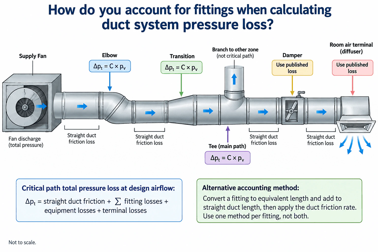
I account for each fitting on every fan to terminal path. With the loss coefficient method, the fitting total pressure loss is Δp_t = C × p_v, where C is the fitting loss coefficient and p_v is the applicable velocity pressure. As an alternative, I can convert the fitting to an equivalent length of straight duct and apply the duct friction rate. I use one method for a fitting, not both. I then add straight duct friction, fitting losses, equipment losses, and terminal losses along each path. The path with the greatest total pressure requirement is the critical path and determines the required fan pressure.
Detailed Explanation
Fittings add pressure loss because they change airflow direction, velocity, or flow distribution. I include those losses when determining the pressure required to move the design airflow from the fan to each room air terminal.
Useful Questions to Ask the Interviewer
Should I use published fitting loss coefficients or an equivalent length method?
Are damper and air terminal pressure losses provided at the design airflow?
Should I evaluate only the supply path, or both supply and return paths when determining the fan pressure requirement?
How to Explain It in an Interview
I first establish the design airflow through each duct section because fitting pressure loss depends on the local airflow and velocity.
For the fitting loss coefficient method, I use:
Δp_t = C × p_v
where Δp_t is the fitting total pressure loss, C is the fitting loss coefficient, and p_v is the velocity pressure at the reference location specified for that fitting. The coefficient must correspond to the actual fitting geometry and flow condition.
I apply this method to fittings such as elbows, transitions, and tees. A tee needs special attention because the straight through path and branch path can have different loss coefficients. In the illustrated design, the main path continues through the tee while the other branch serves another zone. I still calculate both complete paths rather than assuming either path is critical.
For components such as dampers and room air terminals, I use the published pressure loss at the applicable design airflow when reliable manufacturer data are available.
An alternative is the equivalent length method. I convert a fitting loss to an equivalent length of straight duct, add that equivalent length to the actual duct length, and apply the selected straight duct friction rate. I do not also apply a loss coefficient to the same fitting because that would count the fitting loss twice.
I then trace each path from the fan to its terminal and sum the applicable losses:
Total path pressure loss = straight duct friction + fitting losses + equipment losses + terminal losses
The path with the greatest pressure requirement is the critical path. That path establishes the pressure the fan must overcome at the required airflow. The longest physical path is not necessarily the critical path because fitting and component losses may dominate.
I also distinguish total pressure loss from static pressure change. Fitting coefficients commonly describe total pressure loss, while changes in velocity through transitions and branching fittings can also change static pressure. Finally, I verify that the selected fan can provide the required airflow and pressure and that the system can be balanced without unacceptable noise, vibration, leakage, or poor room air delivery.
Why Interviewers Ask This
Interviewers want to see whether I understand that duct system pressure loss includes more than straight duct friction. I should recognize the effects of elbows, transitions, tees, dampers, and terminals, know how to apply fitting loss coefficients or equivalent length, and identify the fan to terminal path with the greatest pressure requirement.
Common interview mistakes
Common mistakes are calculating only straight duct friction, omitting elbows or tees, using the wrong velocity pressure reference for a fitting coefficient, using one tee coefficient for both flow paths, ignoring damper or terminal losses, counting the same fitting with both a loss coefficient and equivalent length, assuming the longest duct run is automatically the critical path, and confusing static pressure change with total pressure loss.
Interview tip
Explain the calculation as a path problem. Start at the fan, follow one path to a terminal, add straight duct and component losses, then compare that total with the other terminal paths. Mention both Δp_t = C × p_v and the equivalent length method, and state that the path with the greatest pressure requirement is the critical path.
Interviewer may ask next
How would you verify that the path you selected is really the critical pressure path?
I would calculate the complete pressure requirement from the fan to every relevant terminal using the same design airflow assumptions and a consistent pressure basis. For each path I would include straight duct friction, applicable fitting losses, equipment losses, damper losses, and terminal losses. I would then compare the path totals. The path with the greatest pressure requirement is the critical path. I would also verify that fitting coefficients and published component losses correspond to the actual geometry and airflow conditions.
What happens if an elbow is replaced with a lower loss fitting?
For the same applicable velocity pressure, a lower fitting loss coefficient reduces the elbow total pressure loss. The pressure requirement of that path therefore decreases. If that path was previously critical, another terminal path could become the new critical path, so I would recalculate and compare the affected path totals before changing the fan pressure requirement.
27. How would you redesign a duct route that clashes with a structural beam without sacrificing system performance?Air Distribution And Duct DesignHard
i Question Details
Evaluate rerouting, duct aspect-ratio changes, offsets, fitting losses, available ceiling depth, noise, access, fire/smoke requirements, and the revised fan-pressure impact before coordinating the change.
Short Interview Answer (30-60 seconds)
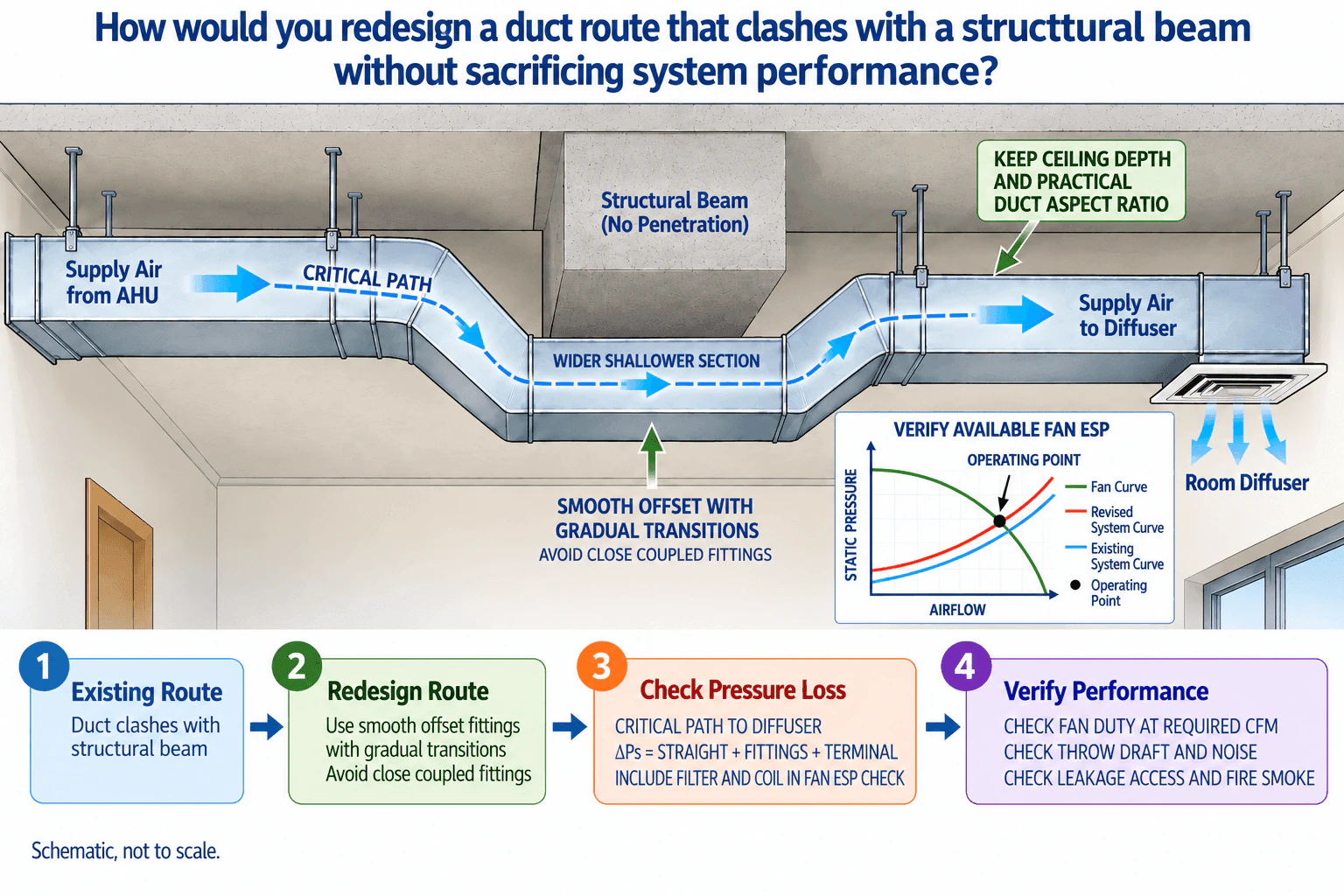
I would first confirm the beam location, available ceiling depth, required airflow, and whether the affected run is on the critical path. I would reroute the duct with a smooth offset and gradual transitions. If vertical clearance is limited, I would use a wider and shallower rectangular section while keeping a practical aspect ratio. Then I would recalculate the critical path pressure losses, including straight duct, fittings, and the terminal, and account correctly for filter and coil losses in the overall fan pressure check without double counting them. I would compare the revised system curve with the fan curve, confirm the required airflow is still available, then check diffuser performance, drafts, noise, leakage, access, and fire and smoke requirements before coordinating the final route.
Detailed Explanation
The goal is to clear the structural beam while preserving the required airflow and acceptable pressure, noise, and room air distribution. I would not simply flatten the duct or add sharp bends because those changes can increase resistance and noise.
Useful Questions to Ask the Interviewer
What airflow must this duct deliver, and is it part of the system critical path?
What ceiling depth and horizontal clearance are available around the beam?
Are there nearby access, diffuser, fire damper, smoke damper, or acoustic constraints that must remain accessible?
How to Explain It in an Interview
I would begin by confirming the required airflow and the physical clearance around the structural beam. I would identify the critical path from the air handling unit to the room diffuser because the revised pressure loss on that path determines whether the fan can still deliver the required airflow.
My preferred redesign would use a smooth offset with gradual transitions. I would avoid closely coupled fittings because consecutive disturbances can increase fitting losses and noise. If the available ceiling depth is limited, I would change the duct proportions to a wider and shallower rectangular section while keeping a practical aspect ratio. The objective is to gain clearance without creating an unnecessarily inefficient duct shape.
Next, I would recalculate the revised critical path. The pressure check would include straight duct friction, the new offset and transition fitting losses, and the terminal pressure loss. Filter and coil pressure losses must also be accounted for in the overall fan pressure requirement according to the fan and equipment selection basis. I would avoid double counting internal equipment losses as external static pressure.
The added fittings and geometry normally increase system resistance, so the revised system curve would move upward relative to the existing system curve. I would compare that revised curve with the fan curve and confirm that the resulting operating point still provides the required airflow and that sufficient fan pressure is available.
Finally, I would verify diffuser airflow and throw, occupied zone drafts, noise, vibration, duct leakage, balancing and service access, and applicable fire and smoke coordination. If the revised fan duty, acoustics, or room delivery are unacceptable, I would revise the route or duct proportions rather than accept reduced performance.
The final coordinated route should therefore clear the beam with smooth fittings and practical duct proportions while maintaining the required airflow and acceptable fan, comfort, access, and acoustic performance.
Why Interviewers Ask This
Interviewers want to see whether I can solve a physical coordination conflict without treating duct routing as only a geometry problem. They are evaluating whether I can preserve required airflow, pressure performance, acoustics, room air delivery, access, and fire and smoke coordination while working within the available ceiling depth.
Common interview mistakes
Common mistakes include flattening the duct without checking the resulting aspect ratio, using abrupt or closely coupled fittings, calculating only straight duct friction while ignoring fitting and terminal losses, failing to identify the critical path, assuming the existing fan automatically has enough pressure, double counting filter or coil losses in external static pressure, confusing static pressure with total pressure, and overlooking diffuser throw, drafts, noise, vibration, leakage, access, and fire and smoke coordination.
Interview tip
Explain the redesign as a sequence of space, duct geometry, pressure, fan, comfort, and coordination checks. Do not stop at saying that the duct can be moved around the beam. Explain how you would prove that the revised route still delivers the required airflow and acceptable room performance.
Interviewer may ask next
How would you validate that the redesigned route will still deliver the required airflow?
I would recalculate the revised critical path pressure loss using the actual duct sizes, straight lengths, fittings, terminal device, and all other components within the defined fan pressure boundary. I would then compare the revised system curve with the fan curve to confirm that the operating point can provide the required airflow. After installation, I would verify performance through appropriate balancing measurements, terminal airflow checks, pressure measurements, and inspection of the installed duct geometry and fittings.
What would you do if the ceiling is still too shallow after changing the duct aspect ratio?
I would compare alternative coordinated routes such as moving horizontally around the beam, shifting the offset location, or dividing the airflow into properly sized parallel ducts where practical. For each option I would repeat the pressure loss, velocity, noise, access, leakage, and fan duty checks. I would choose the route that satisfies the space constraint without creating an unacceptable pressure penalty or degrading room air delivery.
28. How would you compare displacement ventilation with conventional mixing ventilation for a large occupied space?Air Distribution And Duct DesignHard
i Question Details
Compare supply-air location and velocity, temperature stratification, occupied-zone comfort, contaminant removal, load distribution, ceiling height, and control implications.
Short Interview Answer (30-60 seconds)
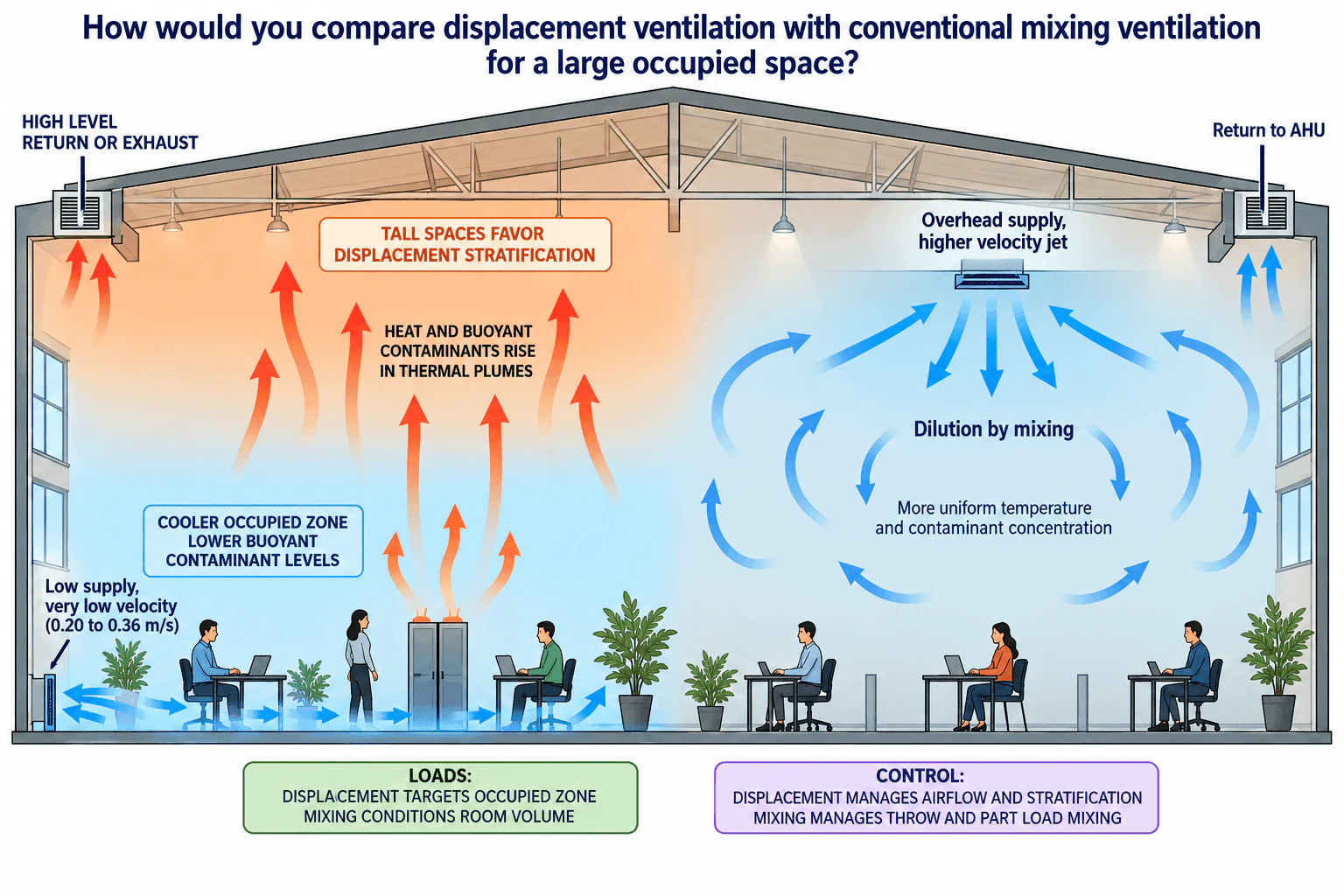
Displacement ventilation supplies cool air at low level and very low velocity. Heat sources create buoyant thermal plumes that carry warm air and buoyant contaminants upward toward a high level return or exhaust, so the occupied zone can remain cooler while the upper zone is warmer. Conventional mixing ventilation normally supplies air from overhead terminals with a higher momentum jet that entrains room air and mixes much of the room volume, giving more uniform temperature and contaminant concentration. For a large space, I would compare ceiling height, sensible load location, diffuser draft risk, contaminant behavior, and part load control before choosing between them.
Detailed Explanation
Displacement ventilation and conventional mixing ventilation use different room airflow principles. Displacement ventilation introduces cool air at floor or low wall level with low momentum. That air spreads through the occupied zone, and heat sources such as people and equipment create buoyant thermal plumes that move warmer air and associated buoyant contaminants upward toward a high level return or exhaust. The result is intentional vertical temperature stratification, with a cooler occupied zone and warmer air above.
Mixing ventilation usually supplies air from overhead diffusers with greater jet momentum. The supply jet entrains surrounding room air and creates circulation through much of the space. This produces more uniform temperature and contaminant concentration than displacement ventilation, provided diffuser selection and airflow are adequate.
Useful Questions to Ask the Interviewer
What are the ceiling height and the vertical distribution of sensible loads?
Are the important contaminants associated with warm buoyant plumes, or are they generated independently of heat sources?
How much will supply airflow and sensible load vary during part load operation?
How to Explain It in an Interview
For supply location and velocity, displacement ventilation normally uses floor or low wall terminals with very low outlet velocity. Mixing ventilation generally uses overhead supply with a higher momentum jet so the diffuser can entrain surrounding air and establish room circulation.
For temperature distribution, displacement ventilation intentionally creates vertical stratification. The occupied zone is cooler while the upper zone is warmer. Mixing ventilation aims for more uniform room temperature by circulating and blending the air.
For comfort, displacement ventilation can keep air speeds low through much of the occupied zone, but occupants located too close to a low level diffuser can still experience local draft. Mixing ventilation depends strongly on diffuser throw and terminal selection so the supply jet mixes effectively without creating excessive occupied zone velocity.
For contaminants, displacement ventilation can produce lower occupied zone concentrations when contaminants are carried upward with buoyant thermal plumes and removed at high level. I would not assume that every contaminant rises. Mixing ventilation mainly relies on dilution, so contaminant concentration tends to be more uniform through the mixed room volume.
Load distribution and ceiling height are important. In a tall space, displacement ventilation can focus conditioning on the occupied zone while allowing a warmer stratified region above. Mixing ventilation generally conditions a larger portion of the room volume. This is why tall spaces can favor displacement stratification when the sensible load pattern is suitable.
Controls must protect the intended airflow pattern. For displacement ventilation, I would control supply airflow and temperature so useful stratification remains without excessive vertical temperature difference or local draft. For mixing ventilation, I would maintain sufficient diffuser throw and room mixing as airflow changes during part load operation.
I would validate either approach by checking occupied zone temperature and air speed, diffuser performance, return location, load distribution, and operation at both design and reduced airflow conditions.
Why Interviewers Ask This
Interviewers want to see whether you can compare two room air distribution strategies by linking supply location and velocity to stratification, occupied zone comfort, contaminant transport, load distribution, ceiling height, and control behavior.
Common interview mistakes
Common mistakes are assuming displacement ventilation produces uniform room temperature, assuming every contaminant rises, ignoring draft risk near low level diffusers, locating the return too low for the intended stratification, treating ceiling height as the only selection criterion, and reducing airflow in a mixing system without checking whether diffuser throw and room mixing remain adequate.
Interview tip
Start with the airflow physics. Explain low level low velocity supply and buoyancy for displacement ventilation, then higher momentum entrainment and dilution for mixing ventilation. After that, compare comfort, contaminant behavior, load distribution, ceiling height, and part load control.
Interviewer may ask next
How would you validate that a displacement ventilation design is working as intended?
I would verify supply airflow and outlet velocity, measure temperature at several heights, check occupied zone air speed and comfort, confirm that thermal plumes are moving heat toward the upper zone, and confirm that the high level return or exhaust removes the stratified upper air. I would also test representative design and part load conditions because reduced airflow or changed heat loads can shift the stratification boundary.
What would change if the large space had a lower ceiling and highly variable loads?
The benefit of displacement stratification would usually be reduced because there is less vertical separation between the occupied zone and the upper warm region. Highly variable loads can also move the stratification boundary and make control more sensitive. A well designed mixing system may then provide more predictable room conditions, but the final choice should still consider diffuser performance, load locations, comfort requirements, and operation across the expected airflow range.
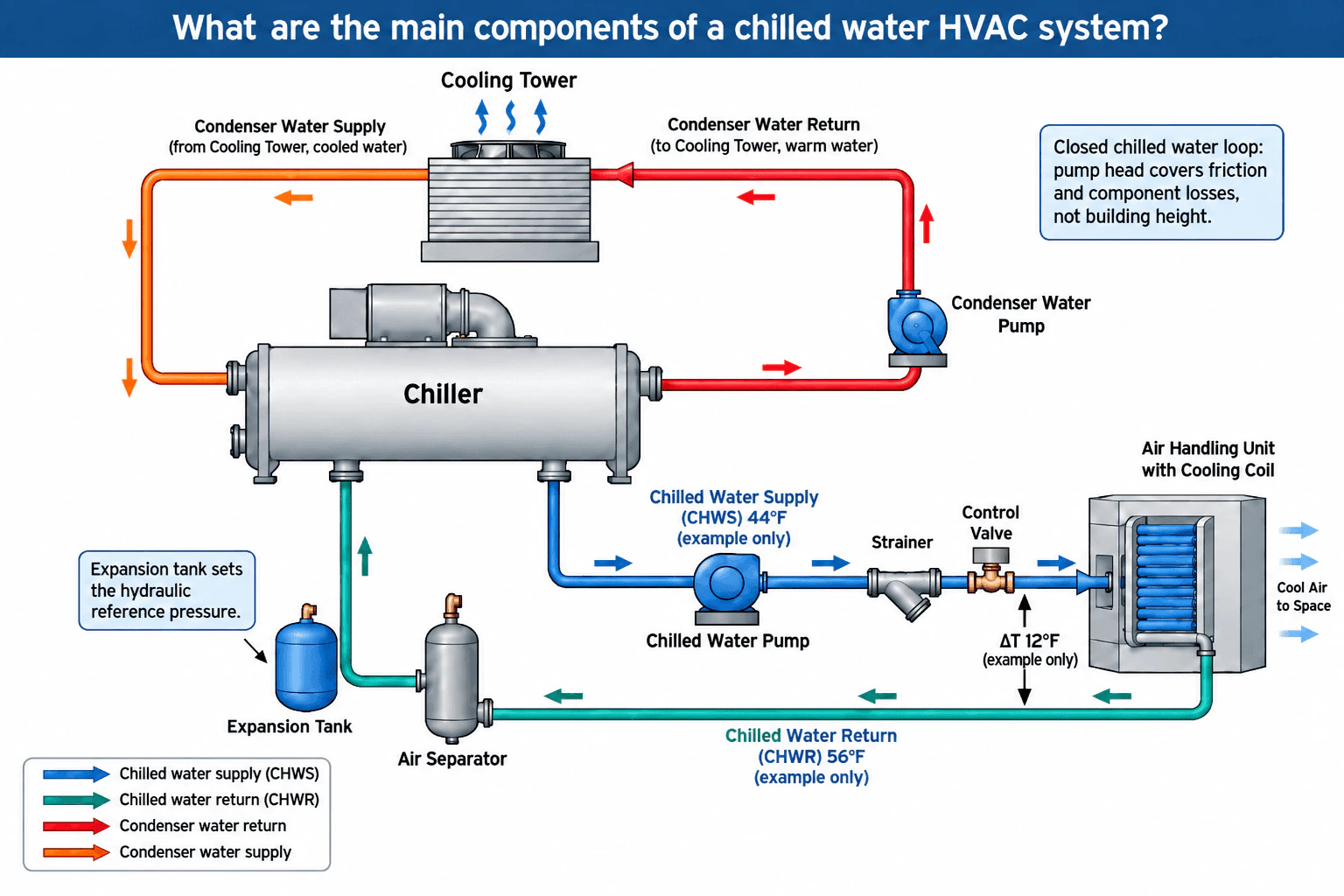
29. What are the main components of a chilled-water HVAC system?Hydronic Systems And Central PlantsEasy
i Question Details
Identify the chiller, pumps, coils, piping, valves, strainers, expansion provisions, controls, and—where applicable—the condenser-water and cooling-tower loop.
Short Interview Answer (30-60 seconds)
The main components are the chiller, chilled water pump, supply and return piping, cooling coils, control valves, strainers, expansion tank, air separator, and system controls. The chiller cools the water, the pump circulates it through the cooling coils, and the warmer return water flows back to the chiller. With a water cooled chiller, a separate condenser water pump and cooling tower loop carries heat from the chiller to the outdoors.
Detailed Explanation
A chilled water HVAC system has two basic functions: produce chilled water and circulate it through the building cooling loads. The chiller removes heat from the chilled water. A chilled water pump then circulates the cold water through supply piping toward the cooling coils in air handling units or other terminal equipment.
Along the distribution circuit, strainers help keep debris out of downstream components, while control valves regulate water flow through the coils according to cooling demand. The cooling coil transfers heat from the air into the chilled water. The warmer water then travels through the return piping back toward the chiller.
The closed chilled water circuit also needs pressure and air management. An expansion tank accommodates changes in water volume and establishes a hydraulic pressure reference. An air separator removes air from the circulating water. These components support stable pressure, reliable circulation, and good heat transfer.
For the example operating condition represented by the system, chilled water supply is 44°F and chilled water return is 56°F, giving a 12°F temperature difference. These are illustrative values rather than universal design requirements.
With a water cooled chiller, a separate condenser water loop is also required. Cooled condenser water leaves the cooling tower and flows to the chiller condenser. After absorbing heat from the refrigeration system, the warmer condenser water is circulated by the condenser water pump back to the cooling tower, where heat is rejected to the outdoor air.
Useful Questions to Ask the Interviewer
Is the chiller air cooled or water cooled?
Is the chilled water pumping arrangement constant flow, variable primary flow, or primary secondary?
Are the stated temperatures design values or illustrative values?
How to Explain It in an Interview
Start at the chiller and trace the chilled water circuit. The chiller removes heat from the water. The chilled water pump sends the cold water through the supply piping, strainer, control valve, and cooling coil. At the coil, heat from the air transfers into the water, so the warmer water returns through the return piping to the chiller.
Then explain the support components. The expansion tank accommodates water volume changes and establishes the hydraulic pressure reference. The air separator removes air from the circulating water. The strainer protects downstream equipment, and the control valve regulates coil flow as the cooling load changes.
For pump selection, determine the required flow and calculate the pressure losses through the critical circuit, including piping, fittings, valves, strainers, coils, and the chiller. In a closed chilled water circuit, circulating pump head is based mainly on friction and component losses. Building height is not simply added to the pump head because the static elevation effects of the supply and return paths largely balance.
If the chiller is water cooled, describe the condenser water circuit separately. Cooled water from the cooling tower enters the chiller condenser, absorbs heat, and returns warmer to the cooling tower. The condenser water pump provides the circulation needed for this loop.
Finally, state that actual temperatures, flow rates, pump duties, minimum chiller flow limits, valve sizing, water treatment, and equipment selections must be based on project conditions and manufacturer requirements.
Why Interviewers Ask This
Interviewers want to see whether you understand the complete chilled water flow path, can identify the main plant and distribution components, and can distinguish the closed chilled water circuit from the condenser water and cooling tower circuit used with a water cooled chiller.
Common interview mistakes
Common mistakes include confusing chilled water with condenser water, reversing condenser water supply and return, forgetting the expansion tank or air separator, treating building height as circulating pump head in a closed chilled water circuit, ignoring strainers and control valves, and assuming illustrative temperatures apply to every project.
Interview tip
Explain the system by tracing one continuous water path at a time. Describe the chilled water circuit first, including the pump, strainer, control valve, cooling coil, return piping, expansion tank, and air separator. Then add the condenser water pump and cooling tower circuit only when discussing a water cooled chiller.
Interviewer may ask next
How would you verify that the chilled water pump is correctly selected?
First determine the required design flow from the cooling duty and design temperature difference. Then calculate the pressure losses through the critical circuit, including piping, fittings, valves, strainers, coils, and the chiller evaporator. Compare that requirement with the pump curve and confirm the operating point, minimum equipment flow requirements, acceptable control valve pressure conditions, and suitable system pressures.
What changes if the system uses an air cooled chiller instead of a water cooled chiller?
The chilled water distribution circuit can remain similar, but the separate condenser water pump, condenser water piping, and cooling tower are normally eliminated. An air cooled chiller rejects heat directly to outdoor air through its condenser coils and fans, so the plant arrangement is simpler but has different efficiency, location, sound, and outdoor temperature considerations.
30. What is chilled-water delta-T, and why is it important?Hydronic Systems And Central PlantsEasy
i Question Details
Define the chilled-water supply-to-return temperature difference and explain its relationship to heat transfer, required flow, and plant performance.
Short Interview Answer (30-60 seconds)
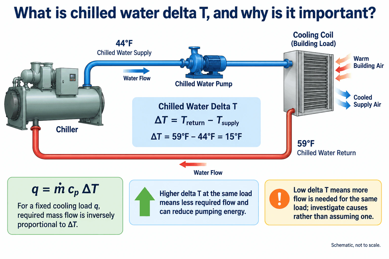
Chilled water delta T is the temperature rise of the water as it absorbs heat from the building. It is calculated as return water temperature minus supply water temperature. In the diagram, 59°F return minus 44°F supply gives a 15°F delta T. From q = ṁ cp ΔT, the same cooling load can be carried with less water flow when delta T is larger. If delta T becomes lower while the load stays the same, more flow is required, which can increase pumping demand and can limit effective plant capacity.
Detailed Explanation
Chilled water delta T is the difference between the return water temperature and the supply water temperature. The water leaves the chiller cold, is moved by the chilled water pump to the cooling coil, absorbs heat from the building load, and returns warmer to the chiller.
For the diagram, the chilled water supply temperature is 44°F and the return temperature is 59°F. Therefore, ΔT = Treturn − Tsupply = 59°F − 44°F = 15°F.
The governing heat balance is q = ṁ cp ΔT, where q is the rate of heat transfer, ṁ is water mass flow rate, cp is the specific heat of water, and ΔT is the chilled water temperature difference.
Useful Questions to Ask the Interviewer
Are the supply and return temperatures measured at the central plant or across the cooling coil?
Should I assume the cooling load remains constant when explaining the relationship between delta T and flow?
Do you want me to discuss only the hydronic relationship, or also the effect on plant capacity and pumping?
How to Explain It in an Interview
Start with the definition. Chilled water delta T is return temperature minus supply temperature. The return water is warmer because it absorbs heat at the cooling coil.
Using the diagram values, the water leaves the chiller at 44°F and returns at 59°F, so the delta T is 15°F.
Then connect delta T to the heat balance q = ṁ cp ΔT. For a fixed cooling load and approximately constant water specific heat, required mass flow is inversely proportional to delta T. A larger delta T therefore allows the same cooling load to be carried with less water flow.
Lower required flow can reduce pumping energy when the pumping system is able to reduce flow accordingly. It can also help the plant deliver more cooling through piping and equipment that have practical flow limits.
If delta T falls while the cooling load remains the same, the required water flow rises. Higher flow can increase pumping demand and can cause pumps, piping, or chillers to approach their flow limits before the intended cooling capacity is delivered.
Low delta T is a symptom, not a diagnosis. I would verify the supply and return temperature measurements, confirm the flow measurement, and examine coil and plant operating conditions before assigning a cause.
The main point is that chilled water delta T directly links heat transfer to required flow. Maintaining the intended delta T helps the plant carry cooling efficiently, while unexpectedly low delta T can increase flow requirements and reduce effective plant performance.
Why Interviewers Ask This
Interviewers want to know whether the candidate understands the hydronic heat balance and can connect chilled water temperature difference to heat transfer, required water flow, pumping energy, and overall plant performance. They also want the candidate to recognize that low delta T is an operating condition that should be investigated using evidence rather than assigned a cause without measurements.
Common interview mistakes
Common mistakes include reversing the supply and return temperatures, confusing temperature difference with an absolute temperature, discussing delta T without connecting it to heat transfer and flow, and assuming that low delta T always has one specific cause. Another mistake is assuming that simply increasing flow will solve a cooling problem without checking the actual load, coil performance, measurements, and equipment flow limits.
Interview tip
Define delta T first, then write q = ṁ cp ΔT and explain the flow relationship. Use the 44°F supply and 59°F return example to show the 15°F temperature difference. Finish by stating that, for the same cooling load, lower delta T requires more flow and that low delta T should be investigated using measured system evidence.
Interviewer may ask next
How would you verify that a reported low chilled water delta T is real?
I would verify the supply and return temperature sensors, confirm that both measurements represent the same hydraulic boundary, and check the water flow and cooling load at the same operating condition. I would then calculate heat transfer using q = ṁ cp ΔT and compare it with other available load information. If the measurements are inconsistent, I would resolve the instrumentation problem before drawing conclusions about the coil or central plant.
What happens if the cooling load stays the same but chilled water delta T drops from 15°F to 10°F?
From q = ṁ cp ΔT, if q and cp remain constant, required mass flow varies inversely with delta T. The new flow is 15 divided by 10, or 1.5 times the original flow. That means about 50 percent more mass flow is required for the same cooling load. The additional flow can increase pumping demand and can move the piping, pumps, or chillers closer to their practical flow limits.
More questions load as you scroll
Disclaimer: This interview guide is for educational and informational purposes only. It is designed to help readers prepare, but it does not guarantee any interview result, hiring decision, offer, or outcome. Interview questions, hiring criteria, and preferred answers can vary by employer, interviewer, industry, location, and time. All answers, examples, and explanations in this guide are suggested examples for interview preparation, not definitive answers or instructions for professional practice. They are based on research and judgment, are provided without warranties of any kind, and should be adapted to the question, role, and applicable laws and professional requirements. Diagrams are simplified illustrations intended to highlight the main concepts and their relationships; actual situations, systems, and practices may be more complex. Alternative approaches may be equally valid or better suited to a particular question, context, or interviewer. To the fullest extent permitted by applicable law, the contributors and publisher are not liable for decisions made, actions taken, or losses incurred based on this guide.
State Laws and Professional Responsibilities: Laws and requirements governing an occupation vary by state and jurisdiction. You are responsible for checking the current laws, licensing requirements, and scope-of-practice rules that apply to your location and role, and for ensuring that your answers and actions comply with them. Adapt examples in this guide to those requirements. This guide is not legal advice.
Content Accuracy and Verification: To the fullest extent permitted by applicable law, we do not represent or warrant that interview guides, questions, answers, examples, or diagrams are accurate, complete, current, error-free, or suitable for any particular purpose. You are responsible for independently reviewing and verifying the information before relying on it.