This interview guide is for educational and informational purposes only. It is designed to help readers prepare, but it does not guarantee any interview result, hiring decision, offer, or outcome. Interview questions, hiring criteria, and preferred answers can vary by employer, interviewer, industry, location, and time. All answers, examples, and explanations in this guide are suggested examples for interview preparation, not definitive answers or instructions for professional practice. They are based on research and judgment, are provided without warranties of any kind, and should be adapted to the question, role, and applicable laws and professional requirements. Diagrams are simplified illustrations intended to highlight the main concepts and their relationships; actual situations, systems, and practices may be more complex. Alternative approaches may be equally valid or better suited to a particular question, context, or interviewer. To the fullest extent permitted by applicable law, the contributors and publisher are not liable for decisions made, actions taken, or losses incurred based on this guide.
State Laws and Professional Responsibilities
Laws and requirements governing an occupation vary by state and jurisdiction. You are responsible for checking the current laws, licensing requirements, and scope-of-practice rules that apply to your location and role, and for ensuring that your answers and actions comply with them. Adapt examples in this guide to those requirements. This guide is not legal advice.
Identity, Image, and Privacy Notice
To respect individual privacy, some names, profile photographs, avatars, biographical details, and other identifying information displayed in this guide may be replaced with pseudonyms, licensed stock images, illustrative avatars, composite images, or representative descriptions. Unless a person is expressly identified as an actual contributor, a displayed name, image, or profile should not be understood as depicting or identifying a specific candidate, interviewer, employee, or other real individual. These representations are provided for editorial and illustrative purposes only and do not imply endorsement, employment, participation, or affiliation with this guide or any company mentioned in it. Any resemblance to an actual person is coincidental.
Company Notice
This guide is an independent educational resource and is not affiliated with, endorsed by, sponsored by, or approved by the company named in this guide. Company names identify reported interview experiences or the employer context of clearly labeled original practice exercises. Interview practices can change without notice, and inclusion of company-specific content does not mean these questions are official, complete, or guaranteed to be asked. To the fullest extent permitted by law, the author, contributors, and publisher are not responsible for outcomes related to use of this material.
Content Accuracy and Verification
To the fullest extent permitted by applicable law, we do not represent or warrant that interview guides, questions, answers, examples, or diagrams are accurate, complete, current, error-free, or suitable for any particular purpose. You are responsible for independently reviewing and verifying the information before relying on it.
Questions or comments?
Contact us for general questions, or share feedback, technical corrections, and comments with the community.
31. How do you size chilled-water flow for a known cooling load and design delta-T?Hydronic Systems And Central PlantsMedium
i Question Details
Describe the heat-balance relationship between load, water flow, fluid heat capacity, and temperature difference, then explain how the result informs pipe and pump selection.
Short Interview Answer (30-60 seconds)
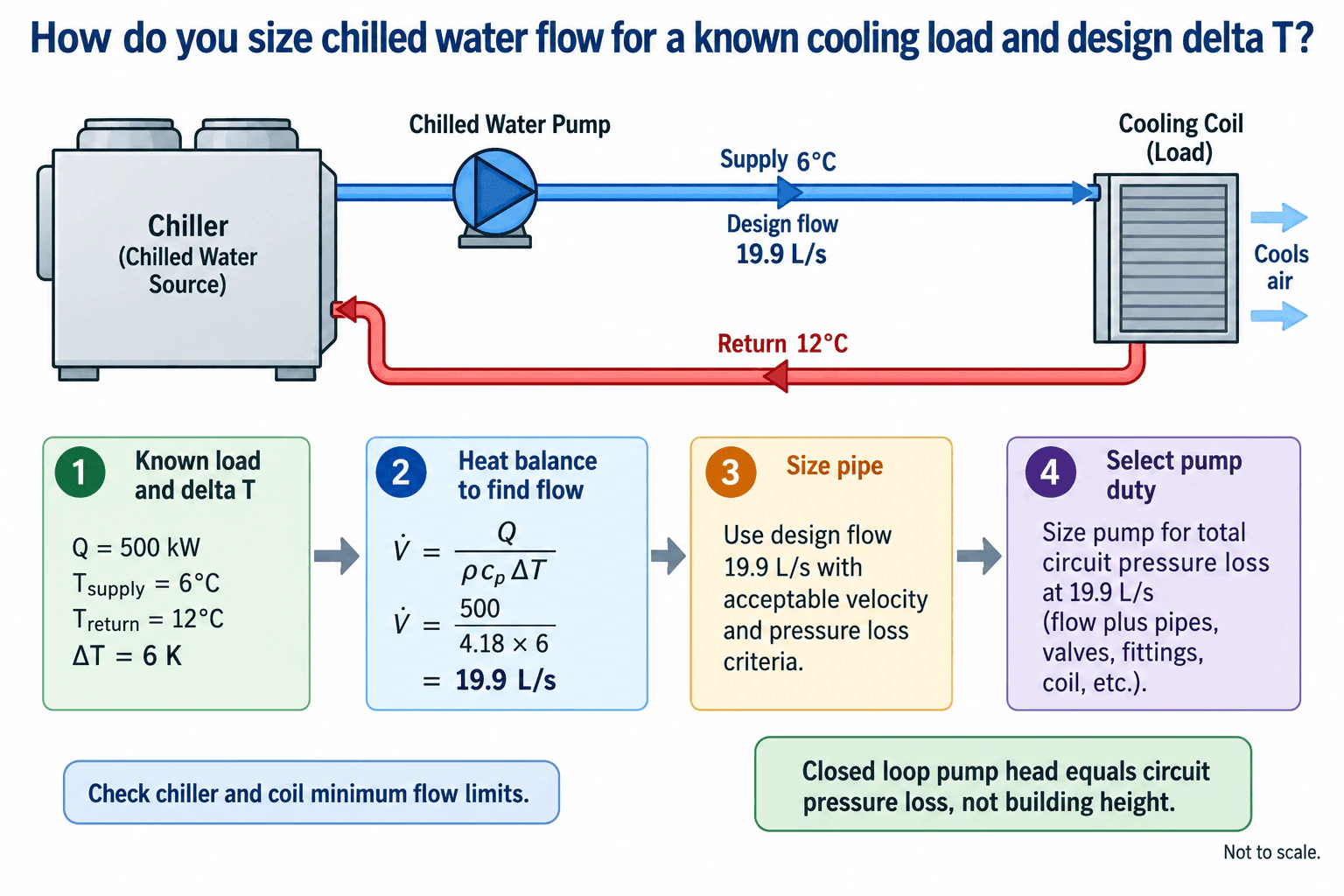
I start with the hydronic heat balance, Q̇ = ṁ cp ΔT, or Q̇ = ρ V̇ cp ΔT for volumetric flow. Therefore, V̇ = Q̇ divided by ρ cp ΔT. In the diagram example, a 500 kW load with 6°C supply water and 12°C return water gives ΔT = 6 K and approximately 19.9 L/s for water. I then size the pipe for that design flow using acceptable velocity and pressure loss criteria, calculate the pressure losses through the complete operating circuit, and select the pump to deliver 19.9 L/s at that circuit pressure loss. I also verify applicable chiller and coil flow limits.
Detailed Explanation
The required chilled water flow comes directly from conservation of energy. For the water side of the cooling coil, Q̇ = ṁ cp ΔT. Since ṁ = ρ V̇, the same relationship can be written as Q̇ = ρ V̇ cp ΔT. Solving for volumetric flow gives V̇ = Q̇ divided by ρ cp ΔT.
For the worked example shown in the diagram, the cooling load is 500 kW. Chilled water is supplied at 6°C and returns at 12°C, so ΔT = 6 K. Using water with cp approximately 4.18 kJ per kg K and density approximately 1000 kg per m³, the required mass flow is 500 divided by 4.18 × 6, which is about 19.9 kg/s. Because the water density is close to 1 kg per L at this condition, the volumetric flow is approximately 19.9 L/s. For a real design, use fluid properties appropriate to the actual water or glycol mixture and operating temperature.
Useful Questions to Ask the Interviewer
Is 500 kW the design cooling load that this chilled water circuit must serve?
Is the circulating fluid plain water or a glycol mixture?
Are there specified velocity, pressure loss, or equipment flow limits that must be followed?
How to Explain It in an Interview
Waterside Method
Start with the known load and design water temperatures. In the example, Q̇ = 500 kW, supply temperature = 6°C, return temperature = 12°C, and ΔT = 6 K.
Apply Q̇ = ρ V̇ cp ΔT and solve for V̇. The result is about 19.9 L/s. For the same cooling load, increasing the design ΔT reduces required flow, while decreasing ΔT increases required flow.
Flow And Pressure Checks
Use 19.9 L/s as the design flow for pipe sizing. Choose the pipe size using the project criteria for water velocity and friction loss. Then calculate pressure loss through the complete active circuit, including straight pipe, fittings, valves, the cooling coil, the chiller evaporator, and other components that the flow passes through.
The pump duty is the required design flow at the total pressure loss of that circuit. The selected pump curve should provide the required operating point when combined with the system resistance.
In a closed hydronic loop, building height is not added directly to the circulating pump head. The static pressure increase needed to raise water on the supply side is balanced by the static pressure decrease as water returns. The circulating pump therefore overcomes friction and component pressure losses.
Plant Reasoning
Check the calculated flow against applicable chiller and coil operating limits, including minimum flow where the equipment manufacturer specifies one. The calculation also assumes the intended 6 K temperature difference is achieved. If measured ΔT is lower than design, do not assume a single cause. Check actual load, supply and return temperatures, water flow, control valve position, and coil performance.
Before final equipment selection, verify the fluid properties, pipe pressure losses, equipment pressure drops, allowable flow ranges, and the pump operating point using the actual project and manufacturer data.
Why Interviewers Ask This
Interviewers want to see whether you can connect the thermal load calculation to the hydraulic design. A strong answer shows that you understand the hydronic heat balance, can convert a known cooling duty and design temperature difference into required water flow, and can then use that flow to size piping and establish the pump duty.
Common interview mistakes
Common mistakes include calculating flow without using the design temperature difference, confusing mass flow with volumetric flow, omitting density when converting between them, using plain water properties for a glycol mixture, choosing pipe size without checking velocity and pressure loss, selecting the pump from flow alone without calculating circuit resistance, adding building height directly to closed loop pump head, ignoring component pressure drops, and failing to check applicable equipment minimum flow limits.
Interview tip
State the heat balance first, define each symbol, calculate the required flow, and then separate pipe sizing from pump selection. Explain that the pipe is selected for the design flow using velocity and pressure loss criteria, while the pump must deliver that flow at the total circuit pressure loss. Mentioning equipment flow limits and explaining why closed loop circulating head is not simply the building height demonstrates practical hydronic design understanding.
Interviewer may ask next
How would you validate the calculated chilled water flow before final equipment selection?
I would confirm the design cooling load, supply and return water temperatures, fluid type, density, and specific heat. I would then compare the calculated 19.9 L/s flow with the allowable flow range for the chiller and coil, calculate pressure losses through the complete active circuit, and verify that the selected pump curve provides the required flow at the resulting system resistance. I would also confirm that the proposed pipe size satisfies the project velocity and pressure loss criteria.
What happens if the design temperature difference increases while the cooling load stays constant?
Required water flow decreases because V̇ = Q̇ divided by ρ cp ΔT. With the cooling load and fluid properties unchanged, increasing ΔT means each unit of water carries more heat, so less water flow is required. That can reduce pipe flow and pumping demand, but the revised supply and return temperatures and lower flow must still remain within the cooling coil and chiller operating limits.
32. What is the purpose of a building management system in HVAC?Controls And Building AutomationEasy
i Question Details
Explain how a building management system monitors and controls HVAC equipment, sensors, actuators, alarms, schedules, and operating data to support comfort and energy performance.
Short Interview Answer (30-60 seconds)
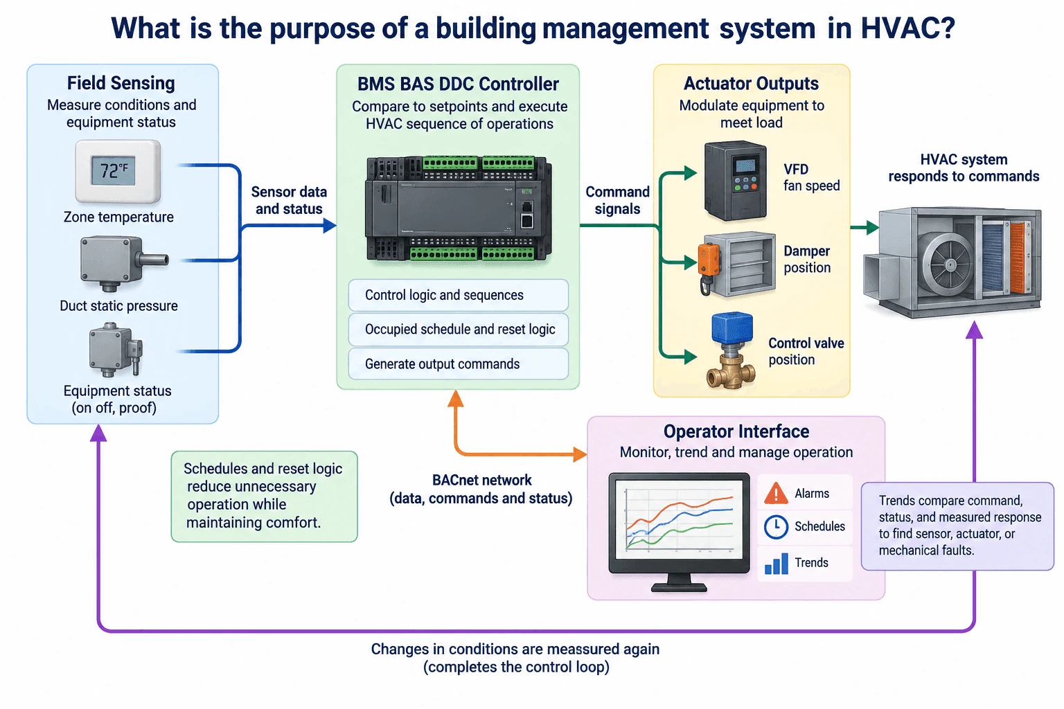
A building management system monitors HVAC conditions and equipment status, applies control logic, schedules, and setpoints, and sends commands to actuators such as VFDs, dampers, and control valves. Sensors then measure the resulting conditions so the controller can continue adjusting the system. Through an operator interface, the BMS also provides alarms, schedules, and trend data. This helps maintain comfort, reduce unnecessary operation, and identify control, sensor, actuator, airflow, or mechanical problems.
Detailed Explanation
A BMS, also called a BAS in many buildings, provides centralized monitoring and supervisory control of HVAC operation. The basic idea is a closed control loop. Field devices measure conditions, the DDC controller compares those conditions with the required operating state, actuators change the HVAC equipment, and sensors measure the response again.
Useful Questions to Ask the Interviewer
Are we discussing a typical commercial BMS controlling equipment such as air handling units and variable air volume systems?
Should I focus on normal occupied operation, or also discuss schedules, alarms, and troubleshooting?
Is BACnet the intended communication protocol for the example?
How to Explain It in an Interview
Start with the inputs. The BMS receives information from field sensors and equipment status points. In this sequence, examples include zone temperature, duct static pressure, and equipment operating status or proof. Sensor location and calibration matter because an incorrect measurement can cause otherwise correct control logic to make the wrong decision.
Explain the controller decision. A DDC controller compares measured conditions with setpoints and applies the sequence of operations. It can also use occupied schedules and reset logic. For example, an occupied schedule can enable normal comfort control, while reset logic can adjust operating targets as load changes instead of operating continuously at fixed maximum conditions.
Explain the outputs. The controller sends commands to actuators. Typical examples are a VFD command that changes fan speed, a damper command that changes airflow, and a control valve command that changes coil water flow. These outputs cause the HVAC system to respond to the current load.
Close the loop. Sensors measure the new conditions after the equipment responds. The controller uses that feedback to determine whether further adjustment is required. Deadbands and stable control logic help prevent unnecessary hunting or rapid command changes.
Explain supervision. The operator interface communicates with the controller over a BACnet network so operators can view and manage operating data, schedules, alarms, commands, status, and trend logs. Trends are especially useful because an engineer can compare a command with the actual status and measured response. If a command changes but the expected response does not occur, the problem may be in the sensor, actuator, airflow path, mechanical equipment, or control sequence.
The overall purpose is to maintain required conditions while coordinating equipment efficiently and giving operators visibility into system operation. Required interlocks, equipment protections, and approved valve or damper fail positions remain part of the control sequence and should not be bypassed by supervisory control.
Why Interviewers Ask This
Interviewers want to confirm that the candidate understands the complete HVAC control loop. That includes how sensors provide operating data, how a DDC controller applies setpoints, schedules, and sequences, how actuators change equipment operation, and how alarms and trend data help operators verify comfort, energy performance, and system behavior.
Common interview mistakes
Common mistakes include describing the BMS only as a monitoring screen, ignoring the feedback loop between sensors and actuators, assuming every fault is a controls fault, and overlooking sensor calibration or equipment proof. Another mistake is treating a commanded position as proof of actual operation. Engineers should compare commands, status points, and measured response using trend data before deciding whether the problem is in the sensor, actuator, sequence, airflow system, or mechanical equipment.
Interview tip
Explain the BMS as one complete control loop: measure conditions, compare them with the required state, command the equipment, measure the response, and use alarms and trends to verify operation. Naming a zone temperature sensor, duct static pressure sensor, VFD, damper actuator, control valve, DDC controller, and BACnet operator interface makes the explanation concrete without making it overly complicated.
Interviewer may ask next
How would you verify that a BMS control sequence is working correctly?
I would review the intended sequence, confirm that the system is in the expected operating mode, and check sensor values for reasonable readings and calibration. Then I would trend the setpoint, measured value, controller command, equipment status, and resulting response. For example, if the controller increases a fan VFD command, I would expect the appropriate equipment status and duct static pressure response. If the command changes but the measured condition does not respond as expected, I would investigate the actuator, sensor, airflow path, or mechanical equipment before changing the control logic.
How can a BMS improve energy performance without sacrificing comfort?
The BMS can use occupied schedules and reset logic so equipment operates according to actual building needs instead of continuously at fixed conditions. It can reduce unnecessary operation during unoccupied periods and adjust targets as load changes while continuing to monitor zone conditions. The engineer should verify the result with trend data and maintain required equipment protections, interlocks, and comfort limits.
33. What are the main components of a typical HVAC control loop?Controls And Building AutomationEasy
i Question Details
Identify the controlled variable, sensor, controller, setpoint, actuator, and controlled device, and explain how feedback closes the loop.
Short Interview Answer (30-60 seconds)
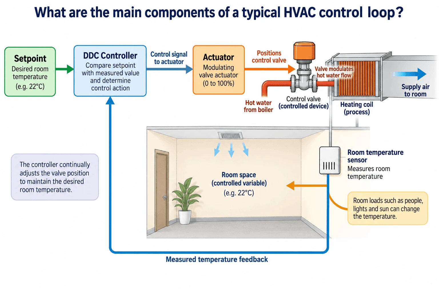
The main components are the setpoint, controlled variable, sensor, controller, actuator, and controlled device. For a room heating loop, room temperature is the controlled variable and the desired temperature is the setpoint. The room sensor sends the measured temperature to the DDC controller. The controller compares the measurement with the setpoint and commands a valve actuator. The actuator positions the control valve, which modulates hot water through the heating coil. The resulting room temperature is measured again and fed back to the controller, closing the loop.
Detailed Explanation
A typical HVAC control loop continuously measures a controlled variable, compares it with a desired setpoint, and adjusts equipment so the measured condition moves toward the setpoint.
In the room heating example, the controlled variable is room temperature and the setpoint is the desired room temperature, such as 22°C. A room temperature sensor measures the actual value and sends the measurement to the DDC controller. The controller compares the measured temperature with the setpoint and determines the required control action. It then sends a control signal to the valve actuator.
The actuator physically positions the control valve. The control valve is the controlled device and modulates hot water flow through the heating coil. The heating coil is part of the physical process that transfers heat to the supply air, which changes the room temperature.
The room sensor then measures the resulting temperature and sends that value back to the controller. This repeated measurement and correction is the feedback path that closes the loop. Disturbances such as occupants, lighting, and sunlight can change the room temperature, so the controller continually adjusts valve position as conditions change.
Useful Questions to Ask the Interviewer
Are we discussing a simple room temperature loop or a specific HVAC system such as an AHU or VAV system?
Should I describe simple proportional control or include PID behavior?
Do you want the answer at the field device level or also in the context of a BAS or BMS?
How to Explain It in an Interview
Start by naming the six main elements: setpoint, controlled variable, sensor, controller, actuator, and controlled device.
Then trace the loop in order. The setpoint represents the desired condition. The sensor measures the actual controlled variable. The controller compares that measurement with the setpoint and determines the required response. The controller output goes to an actuator, which moves the controlled device.
For example, if a room is below its temperature setpoint, the DDC controller can command the valve actuator to open the hot water control valve farther. The valve then allows more hot water through the heating coil. The coil transfers more heat to the supply air, which raises the room temperature. As the room temperature approaches the setpoint, the controller reduces the command.
The key idea is feedback. The room sensor continuously reports the actual temperature back to the controller. Without that feedback, the controller would not know whether its previous action produced the desired result.
If the loop is not maintaining setpoint, I would verify sensor location and calibration, compare the controller command with the actual actuator and valve response, and review trend data. If the valve responds correctly but the room still cannot reach setpoint, I would investigate airflow, hot water availability, coil performance, and available heating capacity.
Why Interviewers Ask This
Interviewers want to see whether the candidate understands the basic structure of feedback control and can distinguish the setpoint, controlled variable, sensor, controller, actuator, controlled device, and physical process. They also want to know whether the candidate can trace cause and effect through an HVAC control loop.
Common interview mistakes
Common mistakes include confusing the setpoint with the controlled variable, treating the sensor as the controller, treating the actuator and control valve as the same component, or forgetting the feedback path. Another mistake is describing only the controller output without explaining how the controlled device changes the physical process and how the resulting condition is measured again.
Interview tip
Trace one simple example from setpoint to sensor, controller, actuator, controlled device, physical process, and back through feedback. Clearly separate the actuator from the device it moves. In this example, the actuator positions the control valve, while the valve modulates hot water flow through the heating coil.
Interviewer may ask next
How would you verify that a room temperature control loop is operating correctly?
I would compare the room temperature trend with the setpoint and review the controller output over time. I would verify that the temperature sensor is correctly located and calibrated, then compare the commanded actuator position with the actual valve response. If the valve responds correctly but the room still cannot reach setpoint, I would investigate airflow, hot water availability, coil performance, and available heating capacity. This helps distinguish sensor, controller, actuator, and valve faults from mechanical system limitations.
What changes if the room temperature starts oscillating around the setpoint?
Oscillation can indicate an overly aggressive control response, excessive delay, sensor problems, actuator or valve issues, or unsuitable controller tuning. I would first verify the sensor, actuator, valve response, and trend data before changing tuning. If PID control is being used, I would then evaluate the proportional, integral, and derivative settings as appropriate, along with system response time and any applicable deadband. The goal is to correct the actual cause rather than hide a mechanical or instrumentation problem with tuning changes.
34. What is an HVAC sensor, and why does sensor location matter?Controls And Building AutomationEasy
i Question Details
Explain how temperature, humidity, pressure, airflow, or occupancy sensors represent controlled conditions and why drafts, stratification, radiant effects, and poor placement can bias readings.
Short Interview Answer (30-60 seconds)
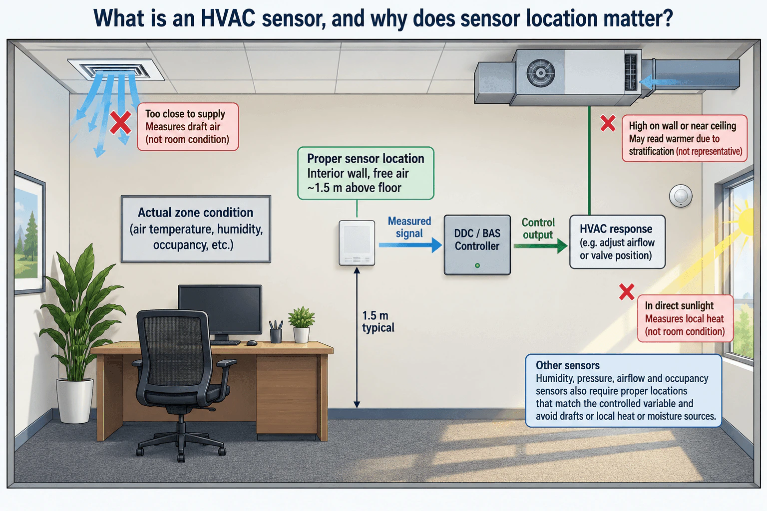
An HVAC sensor measures a physical condition such as temperature, humidity, pressure, airflow, or occupancy and sends that measured signal to the control system. The DDC or BAS controller uses the measurement to decide how the HVAC system should respond, such as adjusting airflow or valve position. Sensor location matters because the reading must represent the condition being controlled. A sensor exposed to a supply air draft, direct sunlight, temperature stratification, or another local disturbance can measure a local condition instead of the true zone condition and cause an unnecessary or incorrect control response.
Detailed Explanation
An HVAC sensor converts a physical condition into a signal that a controller can use. In the control path shown by the diagram, the actual zone condition is represented by the sensor, the measured signal goes to the DDC or BAS controller, and the controller sends a control output that changes the HVAC response, such as airflow or valve position. The control loop is only as useful as the measurement it receives.
Useful Questions to Ask the Interviewer
Which variable is being controlled, such as zone temperature, humidity, pressure, airflow, or occupancy?
Is the sensor intended to represent an occupied zone, a duct condition, or another specific control point?
Are there known local effects such as supply drafts, direct sunlight, moisture sources, radiant heat, or temperature stratification?
How to Explain It in an Interview
A good sensor location measures a representative condition. For a wall mounted zone sensor, that normally means an interior location with freely circulating room air and away from strong local disturbances. The diagram shows about 1.5 m above the floor as a typical example, but the final mounting location should follow the sensor requirements and the intended control application.
A sensor too close to a supply diffuser can be biased because it may measure the supply air draft before that air has mixed with the room. A sensor mounted high on a wall or near the ceiling can be affected by temperature stratification and may not represent conditions in the occupied part of the space. Direct sunlight or another strong radiant heat source can warm the sensor and make its reading different from the surrounding room air.
The same principle applies to other sensors. A humidity sensor should avoid local heat or moisture sources. Pressure and airflow sensors must be placed where the measured condition represents the intended duct, space, or flow point. An occupancy sensor must be positioned so that its sensing area represents the occupancy relevant to the control sequence.
For troubleshooting, I would compare the BAS reading with a suitable independent reference measurement at a representative location. I would inspect the sensor location, verify calibration where appropriate, and review BAS trend data. If the sensor value changes because of a draft, sunlight, stratification, or another local effect rather than because the controlled condition actually changed, the controller may command unnecessary airflow or valve movement. The key idea is that accurate HVAC control requires both a suitable sensor and a representative sensor location.
Why Interviewers Ask This
Interviewers want to know whether the candidate understands that an HVAC control system can only respond correctly when its sensor represents the actual controlled condition. They are testing practical judgment about sensor placement, measurement bias, calibration, and how an unrepresentative reading can cause an otherwise correct DDC or BAS sequence to make the wrong control decision.
Common interview mistakes
Common mistakes include placing a zone sensor directly in a supply air stream, in direct sunlight, near another radiant heat source, high in a space where temperature stratification affects the reading, or near a local heat or moisture source. Another mistake is assuming that a believable sensor value is representative without checking sensor location, calibration, and behavior against an independent reference measurement or BAS trend data.
Interview tip
Explain the control relationship in simple order: actual condition, sensor measurement, DDC or BAS decision, control output, and HVAC response. Then give one placement example, such as a temperature sensor near a supply diffuser reading the draft instead of the mixed room air. This shows that you understand both the sensor and its effect on the control loop.
Interviewer may ask next
How would you verify that a zone temperature sensor is giving a representative reading?
I would compare the sensor with a suitable independent reference measurement taken in the representative occupied area, inspect the sensor location for supply drafts, direct sunlight, radiant heat, or temperature stratification, and verify calibration where appropriate. I would then review BAS trend data to see whether the sensor changes consistently with actual zone conditions and whether controller outputs respond logically.
What happens if a temperature sensor is accurate but installed near a supply diffuser?
The sensor can still provide a biased control input because it may accurately measure the local supply air draft rather than the mixed zone temperature. The DDC or BAS controller can then make an unnecessary control correction, such as changing airflow or valve position, even though the occupied zone condition does not require that response.
35. What does a PID loop do in HVAC controls?Controls And Building AutomationMedium
i Question Details
Explain proportional, integral, and derivative actions in relation to setpoint error and describe symptoms of poor tuning such as hunting, slow recovery, or persistent offset.
Short Interview Answer (30-60 seconds)
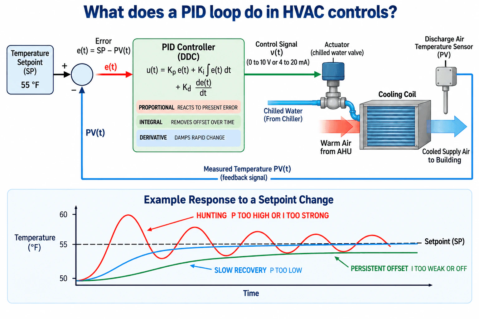
A PID loop continuously compares a measured process variable with its setpoint, calculates the error, and modulates an actuator to reduce that error. In this HVAC example, a discharge air temperature sensor measures the process variable, the DDC controller compares it with a 55 °F setpoint, and the controller modulates a chilled water valve serving a cooling coil. Proportional action reacts to present error, integral action removes persistent offset over time, and derivative action damps rapid change. Poor tuning can appear as hunting, slow recovery, or persistent offset.
Detailed Explanation
A PID loop is a feedback control method that continuously adjusts HVAC equipment so a measured process variable stays near its setpoint. In the illustrated sequence, the controlled variable is discharge air temperature. The setpoint is 55 °F, and a discharge air temperature sensor sends the measured process variable, PV(t), back to the DDC controller.
The controller calculates error as e(t) = SP − PV(t). It combines proportional, integral, and derivative actions to determine the required control output. That output drives the chilled water valve actuator. Changing valve position changes chilled water flow through the cooling coil, which changes discharge air temperature. The sensor then measures the result and closes the feedback loop. The controller action direction must be configured so the valve moves in the corrective direction for the cooling process.
Useful Questions to Ask the Interviewer
Is the loop controlling discharge air temperature, zone temperature, pressure, flow, or another process variable?
Is the controller using full PID or mainly proportional and integral control?
Are trend logs available for setpoint, process variable, controller output, and valve position?
How to Explain It in an Interview
Control Strategy
Proportional action responds to the present error. A larger error produces a stronger immediate control response. If proportional action is too weak, the loop can recover slowly. If it is too aggressive, the process can overshoot and hunt around the setpoint.
Integral action accumulates error over time. Its purpose is to remove persistent offset. If the measured temperature remains away from the setpoint, integral action continues changing the controller output until the remaining error is reduced. If integral action is too weak or disabled, persistent offset can remain. If it is too strong, it can contribute to overshoot and hunting.
Derivative action responds to rapid change in error and adds damping. It can reduce overshoot and oscillation, but it must be applied carefully because noisy sensor signals can make derivative action react excessively.
Control Logic
In this cooling loop, the discharge air temperature sensor reports PV(t) to the DDC controller. The controller compares PV(t) with the 55 °F setpoint, calculates the error, and sends a modulating command to the chilled water valve actuator. Typical analog commands can include 0 to 10 V or 4 to 20 mA. The valve changes chilled water flow through the cooling coil, and the discharge air sensor measures the resulting temperature.
Sequence Checks
Hunting appears as repeated oscillation above and below setpoint and can result from overly aggressive proportional or integral action. Slow recovery means the process takes too long to approach setpoint and can indicate insufficient proportional action. Persistent offset means the process settles away from setpoint and can indicate integral action that is too weak or disabled.
Before changing tuning, verify sensor location and calibration, confirm commanded valve movement matches actual actuator movement, and review trends for setpoint, process variable, controller output, and valve position. A sensor problem, stuck valve, inadequate chilled water flow, airflow limitation, or insufficient coil capacity can resemble poor PID tuning.
Why Interviewers Ask This
Interviewers want to know whether you understand closed loop HVAC control, can explain how proportional, integral, and derivative actions respond to control error, and can recognize poor tuning from symptoms such as hunting, slow recovery, and persistent offset.
Common interview mistakes
Common mistakes include changing PID tuning before verifying the sensor and actuator, assuming every oscillation is caused by tuning, using excessive proportional or integral action that creates hunting, using too little proportional action and getting slow recovery, leaving integral action too weak or disabled so persistent offset remains, and adding derivative action without considering sensor noise.
Interview tip
Explain the loop as one physical feedback path: setpoint, measured process variable, error, controller action, actuator movement, process response, and sensor feedback. Then connect each PID term to the tuning symptoms shown in the response trend: proportional action affects immediate response, integral action removes offset over time, and derivative action adds damping to rapid change.
Interviewer may ask next
How would you determine whether poor temperature control is caused by PID tuning or by an HVAC equipment problem?
Trend the setpoint, measured temperature, controller output, and commanded versus actual valve position. Verify sensor location and calibration first, then confirm the valve actuator moves as commanded. If the controller is requesting additional cooling but discharge air temperature does not respond, investigate chilled water flow, coil capacity, airflow, valve condition, and other mechanical limitations before changing PID tuning. If the equipment responds correctly but the process repeatedly oscillates or recovers too slowly, tuning becomes a stronger suspect.
What would you change if the discharge air temperature repeatedly hunts above and below the 55 °F setpoint?
First rule out sensor noise, valve stiction, actuator problems, and changing mechanical conditions. If the loop itself is too aggressive, reduce proportional action or reduce integral action as appropriate for the controller configuration, then review the trend after each controlled change. Derivative action can add damping in some applications, but it should be used carefully because noisy temperature signals can cause excessive controller movement.
36. How would you reset duct static-pressure setpoint in a VAV system to reduce fan energy while maintaining airflow?Controls And Building AutomationHard
i Question Details
Describe a reset strategy based on terminal-damper demand or critical-zone feedback, including limits, stability, sensor placement, fallback behavior, and commissioning evidence.
Short Interview Answer (30-60 seconds)
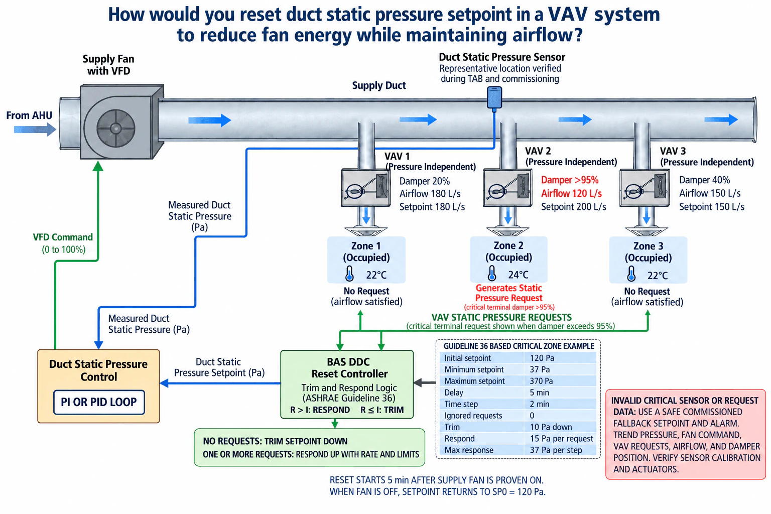
I would use trim and respond logic based on VAV static pressure requests. When the critical terminals are satisfied and there are no requests above the ignored request threshold, the BAS gradually trims the duct static pressure setpoint down. When a critical terminal damper rises above about 95 percent and generates a request, the BAS responds upward within configured limits. A separate PI or PID pressure loop then modulates the supply fan VFD to maintain that reset setpoint. I would verify the duct pressure sensor location and calibration, trend pressure, fan command, VAV requests, airflow, and damper position, and use a safe commissioned fallback setpoint with an alarm if critical sensor or request data becomes invalid.
Detailed Explanation
The objective is to run the supply fan at the lowest duct static pressure that still allows the critical VAV terminals to satisfy their airflow requirements. I would separate the sequence into two control layers. The BAS reset logic determines the duct static pressure setpoint from terminal demand. A PI or PID pressure loop then compares measured duct pressure with that setpoint and adjusts the supply fan VFD.
Useful Questions to Ask the Interviewer
Are the VAV terminals pressure independent, and is reliable damper position and airflow feedback available in the BAS?
Are any zones considered critical and therefore configured with zero ignored requests?
What commissioned static pressure limits and pressure sensor location have already been established?
How to Explain It in an Interview
For the critical zone example shown, a satisfied VAV terminal generates no static pressure request. A terminal with its damper above about 95 percent generates one or more static pressure requests. The example critical terminal also has measured airflow of 120 L/s against a 200 L/s airflow setpoint, so it clearly represents an unsatisfied terminal.
Let R be the number of active requests and I the number of ignored requests. For this critical zone example, I = 0. If R ≤ I, the BAS trims the duct static pressure setpoint downward. If R > I, the BAS responds upward. The response is limited by both the response rate and the maximum permitted change per time step.
The diagram uses a Guideline 36 based teaching example with SP0 = 120 Pa, SPmin = 37 Pa, SPmax = 370 Pa, a 5 minute start delay, and a 2 minute time step. The trim amount is 10 Pa downward. The response amount is 15 Pa per request, with a maximum response of 37 Pa per step. These are example settings and must be commissioned and tuned for the actual system.
The reset output becomes the duct static pressure setpoint. The separate PI or PID pressure loop uses the downstream duct pressure sensor and modulates the fan VFD to maintain that setpoint. Keeping the reset loop slower than the pressure loop helps avoid hunting and unnecessary fan speed changes.
The pressure sensor should be at a representative main duct location and verified during TAB and commissioning rather than assumed correct from location alone. Calibration should also be checked.
Reset begins 5 minutes after the supply fan is proven on. When the fan is off, the example returns the pressure setpoint to SP0 = 120 Pa.
For commissioning, I would trend measured duct pressure, reset setpoint, fan command, VAV requests, measured airflow, airflow setpoint, and damper position. I would verify that satisfied terminals allow pressure to trim down and that a critical request causes a controlled response upward. If critical sensor or request data is invalid, I would use a safe commissioned fallback setpoint, alarm the condition, and verify the sensor, terminal data, and actuator operation before returning to normal reset.
Why Interviewers Ask This
The interviewer is testing whether I can reduce fan energy without sacrificing terminal airflow, convert VAV demand into a stable BAS reset sequence, choose sensible limits and sensor placement, distinguish control faults from real airflow problems, and prove the sequence through commissioning trends.
Common interview mistakes
Common mistakes include holding one fixed duct pressure setpoint, allowing the reset to change too quickly, omitting minimum and maximum limits, using unreliable damper or airflow data, placing the pressure sensor without verifying whether it represents terminal conditions, confusing the slower reset logic with the faster fan pressure loop, and accepting a BAS trend without comparing commanded and actual terminal behavior. Another mistake is allowing invalid critical sensor or request data to continue driving the reset instead of alarming and using a safe commissioned fallback.
Interview tip
Explain the sequence as two connected loops. First, VAV terminal requests reset the duct pressure setpoint. Second, the duct pressure controller modulates the fan VFD to maintain that setpoint. Then state the minimum, maximum, timing, and response limits, explain the critical terminal example, and finish with the trend points you would use to prove that airflow is maintained while fan pressure is reduced.
Interviewer may ask next
How would you prove during commissioning that the reset reduces fan energy without starving zones?
I would trend measured duct pressure, duct pressure setpoint, supply fan command, VAV static pressure requests, measured airflow, airflow setpoint, and damper position. With no active critical requests, the pressure setpoint should gradually trim downward while required terminal airflow remains satisfied. When a critical terminal reaches high damper position and generates a request, the setpoint should rise within the configured response limits and the terminal airflow should recover. I would also test the minimum and maximum limits, pressure sensor calibration, the 5 minute startup delay, the fan off state, and the fallback alarm behavior.
What would you change if many noncritical VAV terminals frequently generate requests from short disturbances?
I would first check terminal calibration, airflow setpoints, actuator operation, and whether the disturbance represents a real mechanical or airflow problem. For a noncritical system, I could then tune the ignored request count, time step, trim amount, response amount, and maximum response so brief requests do not cause excessive pressure increases. Critical zones may still use zero ignored requests. I would confirm the final tuning with trends so the reset remains stable while preserving required airflow.
37. How would you integrate chiller-plant staging with variable-flow pumping and minimum-flow protection?Controls And Building AutomationHard
i Question Details
Describe the monitored plant variables, lead/lag logic, staging criteria, flow limits, differential-pressure control, bypass or minimum-flow strategy, proof conditions, alarms, and transition stability.
Short Interview Answer (30-60 seconds)
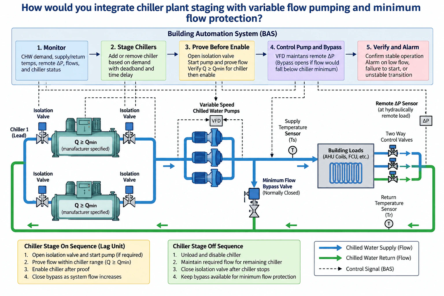
I would coordinate the plant through the BAS using chilled water demand, supply and return temperatures, remote differential pressure, chilled water flow, pump status, isolation valve status where available, and chiller proof signals. Variable speed pumps would maintain the remote differential pressure setpoint. A normally closed minimum flow bypass valve would modulate open only when system flow would otherwise fall below the minimum required by the operating chillers. Chillers would stage using sustained demand with deadband and time delay. Before enabling a lag chiller, I would establish its hydraulic path, start the required pump, prove acceptable flow, and then enable it. I would alarm low flow, failed starts, loss of proof, and unstable transitions and verify the sequence using trends.
Detailed Explanation
The key is to coordinate capacity staging, distribution pressure control, and minimum evaporator flow protection as one sequence. The pump loop serves building demand, while the bypass protects the operating chillers from insufficient flow.
Useful Questions to Ask the Interviewer
Is this a variable primary flow plant, and does each chiller have a dedicated pump or a shared variable speed pump arrangement?
What are the manufacturer specified minimum and maximum evaporator flow limits for each chiller?
Which BAS points are available for plant flow, remote differential pressure, temperatures, pump status, isolation valves, chiller commands, and proof signals?
How to Explain It in an Interview
I would first define the monitored variables. The BAS should monitor chilled water demand, supply temperature, return temperature, remote differential pressure, chilled water flow, pump status, chiller command and run status, and isolation valve status where available. Sensor location and calibration are important because bad flow or pressure measurements can make the sequence unstable.
During normal operation, the variable speed chilled water pumps use a PID loop to maintain the remote differential pressure setpoint. The remote sensor should represent a hydraulically demanding part of the system so pump speed follows actual building demand.
Chiller staging should use sustained demand with deadband and time delay. Lead and lag assignments can rotate according to the plant operating strategy, but equipment availability and protection interlocks always take priority.
When adding a lag chiller, the BAS opens the required isolation valve and starts the associated pump if the piping arrangement requires one. It then proves that flow through the chiller is within the permitted range. Only after flow is proven should the chiller receive its enable command.
The minimum flow bypass valve is normally closed when system demand provides adequate flow. If two way coil valves close and total system flow approaches the minimum required by the operating chillers, the bypass valve modulates open so chiller flow stays at or above the manufacturer specified minimum. Pump speed continues to regulate remote differential pressure. These are separate control objectives.
When removing a chiller, I would unload and disable it, maintain enough flow for the remaining chiller, then close the stopped chiller isolation valve according to the equipment sequence. Deadband and time delay reduce rapid restaging.
I would alarm low flow, failure to start, loss of proof, and persistent unstable operation. Trend logs of flow, differential pressure, pump speed, bypass position, temperatures, commands, and actual equipment states would verify that transitions remain stable and that commanded states match actual operation.
Why Interviewers Ask This
Interviewers want to see whether you can coordinate chiller capacity, variable chilled water flow, differential pressure control, minimum evaporator flow protection, proof conditions, alarms, and stable equipment transitions as one BAS sequence rather than as independent control loops.
Common interview mistakes
Common mistakes include enabling a chiller before proving adequate evaporator flow, trying to use pump speed as the minimum flow protection mechanism, locating the differential pressure sensor where it does not represent system demand, omitting deadband or time delay, closing an isolation valve too early during a stage off transition, ignoring manufacturer flow limits, and trusting BAS commands without checking actual proof and trend data.
Interview tip
Explain the sequence in operating order: monitor demand, decide whether capacity must change, establish the hydraulic path, prove flow, enable or disable the chiller, let the pump maintain remote differential pressure, use the bypass only for minimum flow protection, and verify the transition with proof points, alarms, and trends.
Interviewer may ask next
How would you verify that the minimum flow protection sequence is working correctly?
I would trend total chilled water flow, chiller status, pump speed, remote differential pressure, bypass valve command and position, and relevant temperatures during low load operation and staging events. I would confirm that the bypass begins opening before operating chiller flow falls below the manufacturer specified minimum, that pump speed continues to respond to remote differential pressure, and that the chiller retains its required flow proof. I would also compare commanded and actual states to separate a control problem from a sensor, actuator, or mechanical problem.
What would you change if adding a second chiller caused a sudden redistribution of flow through the operating chiller?
I would slow and coordinate the transition so the new hydraulic path is established before the lag chiller is enabled. Valve position, pump operation, and chiller enable timing should be sequenced so each operating chiller remains within its permitted flow range. Deadband, time delay, and controlled actuator movement can reduce abrupt changes. If acceptable flow cannot be maintained, the BAS should inhibit or abort the staging command rather than override the chiller protection limits.
38. What does kW per ton measure for a cooling plant?Energy Efficiency And SustainabilityEasy
i Question Details
Explain that kW per ton relates electrical input to delivered cooling and identify why it is useful for comparing plant operating efficiency at specific conditions.
Short Interview Answer (30-60 seconds)
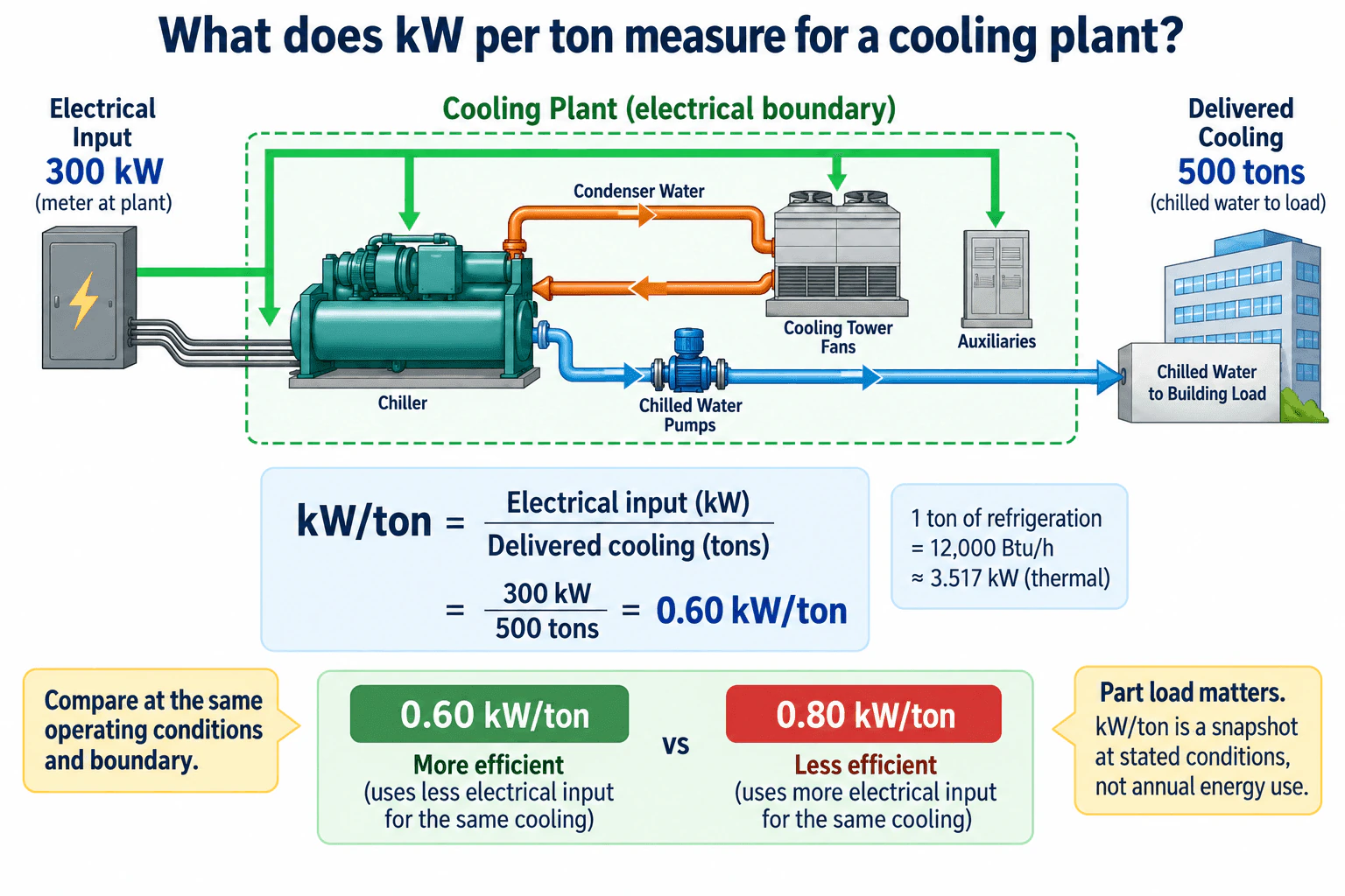
kW per ton measures how much electrical power a cooling plant uses for each ton of cooling it delivers. It is calculated as electrical input in kW divided by delivered cooling in refrigeration tons. A lower kW per ton generally indicates better operating efficiency when the plant boundary and operating conditions are the same. For example, a plant using 300 kW while delivering 500 tons operates at 0.60 kW per ton. Because plant efficiency changes with load and conditions, the value should be compared at stated operating conditions rather than treated as annual energy use.
Detailed Explanation
kW per ton is an operating efficiency metric that relates electrical power input to useful cooling output at a stated operating condition.
Useful Questions to Ask the Interviewer
Are we measuring the complete cooling plant electrical boundary or only the chiller?
At what cooling load and operating conditions should the comparison be made?
Is the goal to compare operating points or understand performance over time?
How to Explain It in an Interview
For a defined cooling plant boundary:
kW/ton = Electrical input in kW ÷ Delivered cooling in tons
One refrigeration ton equals 12,000 Btu/h, which is approximately 3.517 kW of thermal cooling capacity.
Using the worked example, the plant electrical input is 300 kW and the delivered cooling is 500 tons:
300 kW ÷ 500 tons = 0.60 kW/ton
The measurement boundary matters. The diagram shows the chiller, chilled water pump, cooling tower fans, and auxiliaries inside the cooling plant electrical boundary. It also shows a separate condenser water loop between the chiller and cooling tower, while the chilled water path carries cooling from the chiller through the chilled water pump to the building load.
For the same delivered cooling, a lower kW per ton means less electrical input is required. Therefore, 0.60 kW per ton is more efficient than 0.80 kW per ton when both values use the same boundary and comparable operating conditions.
Part load behavior matters because chiller power, pump power, tower fan power, condenser water conditions, and cooling load can all change during operation. A single kW per ton value is therefore a snapshot at stated conditions, not a direct measure of annual energy consumption.
For a valid comparison, I would confirm the electrical boundary, cooling output measurement, load, and operating conditions before comparing the values.
Why Interviewers Ask This
Interviewers want to know whether the candidate understands how cooling plant electrical input relates to useful cooling output, can define the measurement boundary, and can compare operating efficiency only when the operating conditions are comparable.
Common interview mistakes
Common mistakes include comparing values from different electrical boundaries, treating chiller kW per ton as complete plant kW per ton, comparing different loads or condenser conditions without context, assuming one operating point represents annual energy use, and claiming savings without verifying both electrical input and cooling output.
Interview tip
Start with the ratio of electrical input to delivered cooling, define the plant boundary, show one simple numerical example, and then explain that lower kW per ton is better only when the boundary and operating conditions are comparable. Mention part load behavior to show that you understand real plant operation.
Interviewer may ask next
What should you verify before comparing the kW per ton of two cooling plants?
Verify that both measurements use comparable electrical boundaries, cooling output definitions, cooling loads, and operating conditions. Also verify how electrical power and cooling tons were measured. A complete plant value should not be compared directly with a value that represents only chiller power.
Why can a plant with good kW per ton at one operating point still have high annual energy use?
Because kW per ton describes efficiency at a particular operating condition. Annual energy also depends on operating hours, cooling load profile, part load performance, schedules, controls, weather, and other changing conditions. Representative trending is needed to understand performance over time.
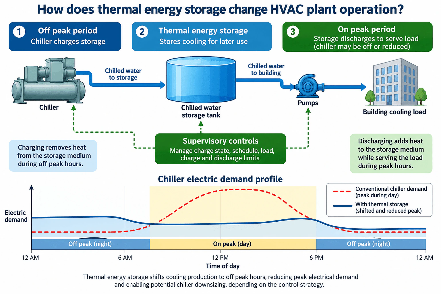
39. How does thermal energy storage change HVAC plant operation?Energy Efficiency And SustainabilityMedium
i Question Details
Explain how cooling or heating production can be shifted in time, identify charging and discharging modes, and discuss impacts on peak electrical demand, equipment sizing, and controls.
Short Interview Answer (30-60 seconds)
Thermal energy storage lets an HVAC plant separate the time when heating or cooling is produced from the time when the building needs it. In the chilled water example, the chiller charges the storage tank during an off peak period. During the on peak period, stored cooling is discharged through the chilled water system to serve the building, so the chiller can operate at reduced capacity or, with sufficient storage, remain off. This shifts electrical demand away from the peak and may allow smaller production equipment, but storage capacity, charging time, pumps, equipment limits, and controls must all be coordinated.
Detailed Explanation
Thermal energy storage adds time shifting to HVAC plant operation. Instead of requiring all heating or cooling production to occur when the building load occurs, the plant can produce thermal energy earlier, store it, and recover it later. The diagram shows the cooling case with a chiller, chilled water storage tank, pumps, building cooling load, and supervisory controls. The same operating principle can be applied to heating storage, where heat is produced and stored before it is needed.
Useful Questions to Ask the Interviewer
Is the storage intended for full peak shifting or partial peak reduction?
What peak demand period and charging window should the control sequence target?
Are we evaluating peak electrical demand only, or also annual energy, equipment capacity, operating cost, and carbon impact?
How to Explain It in an Interview
Efficiency Strategy
During charging, the chiller produces chilled water during an off peak period and removes heat from the storage medium. The storage tank holds usable cooling capacity for later. Charging therefore moves part of the chiller electrical load into the selected charging period.
During discharging, the storage system supplies chilled water to the building cooling load through the pumping system. Heat from the building is absorbed into the chilled water, so the storage medium gains heat as its stored cooling is used. With full storage operation the chiller may remain off for part of the peak period. With partial storage operation the chiller and storage serve the load together.
Savings Logic
The main benefit is load shifting. Cooling production is moved away from the electrical peak, reducing the chiller demand that occurs during the target peak period. Thermal storage does not automatically reduce the building cooling requirement or guarantee lower annual energy use.
Storage can also affect equipment sizing. If stored cooling is intentionally used to meet part of the design peak, the required chiller capacity may be smaller than in a plant that must meet the entire peak directly. That decision depends on the load profile, required storage capacity, available charging hours, redundancy needs, and equipment limits.
Energy Tradeoffs
Supervisory controls manage storage charge state, schedule, building load, pumps, and charge and discharge limits. Poor scheduling can leave too little stored cooling for the peak period or create a new electrical peak while charging.
The evaluation should also include chiller part load performance, pump energy, storage losses, tariff structure, comfort requirements, and operating constraints. I would validate the strategy using measured load and electrical demand data and confirm that the control sequence maintains required building conditions before estimating savings.
Why Interviewers Ask This
Interviewers want to see whether the candidate understands that thermal energy storage changes when heating or cooling is produced rather than changing the building load itself. They are also testing judgment about charging, discharging, peak electrical demand, equipment capacity, pumping, storage limits, and supervisory controls.
Common interview mistakes
Common mistakes are assuming thermal storage automatically reduces annual energy use, confusing the building peak cooling load with peak electrical demand, ignoring the electrical load added during charging, sizing storage without checking the available charging window, assuming the chiller can always remain off during discharge, and overlooking pump energy, storage losses, chiller part load performance, or storage charge limits.
Interview tip
Explain the sequence in time: charge during the selected off peak period, store cooling, discharge during the peak period, and let supervisory controls coordinate the chiller, storage tank, pumps, and building load. Then clearly separate peak demand reduction from annual energy savings and explain that possible chiller capacity reduction depends on the selected storage strategy.
Interviewer may ask next
How would you verify that the storage system is actually reducing peak electrical demand?
I would compare measured electrical demand and plant operating data for comparable conditions before and after the storage strategy is implemented. I would review building cooling load, chiller power, pump power, storage charge state, charging and discharging periods, weather, occupancy, and the utility demand interval. The key check is whether cooling production has moved away from the target peak without creating another unacceptable demand peak or compromising building conditions.
What changes if the storage tank can cover only part of the peak cooling load?
The plant uses partial storage operation. During the peak period, the storage system and chiller operate together, with storage carrying part of the cooling load and the chiller carrying the remainder. This can still reduce peak electrical demand and may reduce required chiller capacity, but the controls must coordinate chiller output and storage discharge so the stored cooling lasts through the intended peak period.
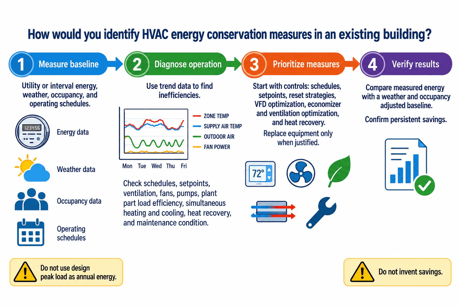
40. How would you identify HVAC energy-conservation measures in an existing building?Energy Efficiency And SustainabilityMedium
i Question Details
Review schedules, setpoints, ventilation, fan and pump operation, plant efficiency, simultaneous heating and cooling, heat recovery, maintenance condition, and trend data before recommending measures.
Short Interview Answer (30-60 seconds)
I would use four steps. First, establish a measured baseline from utility or interval energy data together with weather, occupancy, and operating schedules. Second, diagnose operation using trend data and field checks for schedules, setpoints, ventilation, fans, pumps, plant part load efficiency, simultaneous heating and cooling, heat recovery, and maintenance condition. Third, prioritize controls and operational measures such as reset strategies, VFD optimization, economizer and ventilation optimization, and heat recovery before equipment replacement. Finally, verify persistent savings against a baseline adjusted for weather, occupancy, and important operating changes.
Detailed Explanation
I would treat this as a measured energy audit rather than starting with a list of equipment replacements. The basic sequence is to measure the baseline, diagnose operation, prioritize measures, and verify the results. I would not use design peak load as annual energy consumption, and I would not claim savings without supporting data or analysis.
Useful Questions to Ask the Interviewer
What utility, interval meter, BAS trend, occupancy, weather, and operating schedule data are available?
Are there comfort, ventilation, maintenance, or equipment constraints that must remain unchanged?
Is the main objective annual energy reduction, peak demand reduction, operating cost reduction, carbon reduction, or a combination?
How to Explain It in an Interview
First, I would measure the baseline. I would review utility or interval energy data together with weather, occupancy, and operating schedules so I understand how the building actually uses energy.
Second, I would diagnose operation. I would use trend data and field observations to check schedules, setpoints, ventilation, fan and pump operation, plant efficiency at part load, simultaneous heating and cooling, heat recovery opportunities, and maintenance condition. For example, I would look for equipment running when spaces are unoccupied, excessive static pressure or flow, poor reset control, heating and cooling occurring at the same time, failed sensors, dirty coils, or malfunctioning dampers and valves.
Third, I would prioritize measures. I would usually investigate controls and operational changes before major equipment replacement. Typical measures include correcting schedules and setpoints, applying suitable reset strategies, optimizing VFD controlled fans and pumps, improving economizer and ventilation control, eliminating unnecessary simultaneous heating and cooling, using heat recovery where appropriate, and correcting maintenance faults. Equipment replacement would follow when condition, efficiency, capacity, or life cycle economics justify it.
I would compare measures using annual energy, peak demand, utility cost, carbon impact where relevant, equipment limits, maintenance effects, and comfort consequences. Ventilation and safety requirements must remain satisfied. Simple payback can help with screening, but it does not capture equipment life, maintenance costs, future energy prices, or other life cycle effects.
Finally, I would verify the result. I would compare measured post improvement energy with an appropriate baseline adjusted for weather, occupancy, and major operating changes. I would confirm that the intended control or equipment change is actually operating correctly and that the savings persist over time. I would document assumptions, tariff basis, uncertainty, and any changes that affect the comparison.
Why Interviewers Ask This
Interviewers want to see whether I can identify practical energy conservation measures from measured building performance instead of jumping directly to equipment replacement. They are evaluating whether I can establish a defensible baseline, diagnose operating problems, understand part load behavior, prioritize controls and maintenance opportunities, protect ventilation and comfort requirements, and verify that savings persist.
Common interview mistakes
Common mistakes include estimating savings before establishing a measured baseline, treating design peak load as annual energy consumption, judging equipment only by nameplate efficiency instead of part load behavior, overlooking schedules and simultaneous heating and cooling, recommending equipment replacement before checking controls and maintenance, reducing ventilation without confirming requirements, ignoring weather or occupancy changes during verification, and presenting assumed savings as measured results.
Interview tip
Use the same four step structure shown in the diagram: measure the baseline, diagnose operation, prioritize measures, and verify results. Mention part load plant efficiency, simultaneous heating and cooling, controls first optimization, and weather and occupancy adjusted verification. This keeps the answer practical and shows that recommendations come from measured building operation.
Interviewer may ask next
How would you validate that an energy conservation measure actually produced savings?
I would define the measurement boundary and baseline before implementation, identify the variables that materially affect energy use, and collect appropriate baseline and post improvement data. Depending on the measure, I could use utility meters, interval meters, BAS trends, temporary measurements, or a combination. I would adjust for relevant changes such as weather, occupancy, schedules, or major operating changes. I would also verify that the intended control or equipment change is actually operating as expected. Savings should be reported with documented assumptions and uncertainty rather than treated as exact when the available data do not support that precision.
What would you do if the owner wanted the lowest cost measures first?
I would prioritize operational and controls measures that can reduce waste with limited capital investment. I would investigate schedule corrections, setpoint adjustments, reset strategies, VFD optimization, economizer and ventilation control, simultaneous heating and cooling, sensor or valve faults, heat recovery opportunities, and maintenance deficiencies. I would estimate the energy and cost effect using the measured baseline while maintaining comfort, ventilation, equipment, and safety limits. Higher capital equipment replacement would remain an option when its additional savings, equipment condition, maintenance benefits, and life cycle economics justify the investment.
More questions load as you scroll
Disclaimer: This interview guide is for educational and informational purposes only. It is designed to help readers prepare, but it does not guarantee any interview result, hiring decision, offer, or outcome. Interview questions, hiring criteria, and preferred answers can vary by employer, interviewer, industry, location, and time. All answers, examples, and explanations in this guide are suggested examples for interview preparation, not definitive answers or instructions for professional practice. They are based on research and judgment, are provided without warranties of any kind, and should be adapted to the question, role, and applicable laws and professional requirements. Diagrams are simplified illustrations intended to highlight the main concepts and their relationships; actual situations, systems, and practices may be more complex. Alternative approaches may be equally valid or better suited to a particular question, context, or interviewer. To the fullest extent permitted by applicable law, the contributors and publisher are not liable for decisions made, actions taken, or losses incurred based on this guide.
State Laws and Professional Responsibilities: Laws and requirements governing an occupation vary by state and jurisdiction. You are responsible for checking the current laws, licensing requirements, and scope-of-practice rules that apply to your location and role, and for ensuring that your answers and actions comply with them. Adapt examples in this guide to those requirements. This guide is not legal advice.
Content Accuracy and Verification: To the fullest extent permitted by applicable law, we do not represent or warrant that interview guides, questions, answers, examples, or diagrams are accurate, complete, current, error-free, or suitable for any particular purpose. You are responsible for independently reviewing and verifying the information before relying on it.