197 Mechanical Engineer Interview Questions & Answers

83 top • 12 Boeing • 9 Bosch • 12 Caterpillar • 9 Ford • 12 GE Aerospace • 12 Honeywell • 11 John Deere • 10 Lockheed Martin • 10 Rolls-Royce • 4 Siemens Energy • 10 Tesla • 3 Trane Technologies

Mechanical Engineer icon

Questions with Detailed ExplanationsWith Detailed Explanations

(Last Updated: September 13, 2026)

11. Which stainless-steel grades are commonly used in manufacturing?Materials And Material SelectionEasy

Short Interview Answer (30-60 seconds)

Common stainless-steel grades used in manufacturing include 304 and 316 austenitic stainless steels, 430 ferritic stainless steel, and 410 and 420 martensitic stainless steels. 304 is a common general-purpose choice because it combines good corrosion resistance with good formability and weldability. 316 is typically selected when better resistance to chloride-containing or more aggressive environments is required. 430 is often used for less aggressive environments where moderate corrosion resistance and lower alloy cost are important. 410 and 420 are used when heat-treatable strength, hardness, or wear resistance is more important. The final grade should be selected from the actual environment, temperature, mechanical requirements, fabrication process, and required service life.

Detailed Explanation

Stainless steel is a family of corrosion-resistant iron-based alloys, so there is no single grade that is best for every manufactured component. A useful way to answer this question is to group commonly used grades by stainless-steel family and then explain what drives the selection.

304 is one of the most widely used austenitic stainless steels. It is a common general-purpose manufacturing choice because it offers a useful combination of corrosion resistance, ductility, formability, and weldability in many ordinary service environments. Low-carbon 304L is also commonly specified for welded fabrication when reducing susceptibility to sensitization-related corrosion is important.

316 is another widely used austenitic stainless steel. Compared with 304, it is generally selected when improved resistance to chloride-containing or other more aggressive environments is required. 316L is a common low-carbon version used for welded components for the same general sensitization-control reason. The added corrosion resistance usually comes with higher material cost, so it should be justified by the service conditions rather than selected automatically.

430 is a common ferritic stainless steel. It provides useful corrosion resistance in relatively mild environments and can be an economical choice where the higher corrosion resistance and fabrication characteristics of common austenitic grades are unnecessary. Its mechanical and fabrication behavior differs from 304 and 316, so substitution should not be based on cost alone.

410 and 420 are common martensitic stainless steels. Unlike 304, 316, and 430, these grades can be hardened by suitable heat treatment. They are selected when hardness, wear resistance, or higher heat-treated strength is important. Their corrosion resistance is generally lower than that of common austenitic grades, so the service environment still has to be checked carefully.

The grade name alone does not completely define performance. Material condition, heat treatment, surface finish, welding history, fabrication method, temperature, and exposure environment can all affect service behavior. For example, choosing between 304 and 316 should be based on the actual corrosive environment, while choosing between an austenitic and martensitic grade may depend more strongly on whether ductility and fabrication or hardness and wear resistance are the dominant requirements.

Useful Questions to Ask the Interviewer
  • What environment will the component operate in: indoor atmosphere, water, chemicals, salt, or chloride exposure?
  • What operating-temperature range is expected?
  • Which properties matter most: strength, toughness, ductility, hardness, wear resistance, or corrosion resistance?
  • Will the part be welded, formed, machined, cast, or heat treated?
  • Are there requirements for surface finish, cleanliness, magnetic behavior, availability, or cost?
  • Will the stainless steel contact dissimilar metals, creating a possible galvanic-corrosion concern?
  • What failure mechanism is most important to prevent, such as general corrosion, localized corrosion, wear, cracking, or distortion?
How to Explain It in an Interview

I would start with the common stainless-steel families. For general fabricated components, 304 is a common baseline because it offers good corrosion resistance, ductility, formability, and weldability. If welded fabrication makes sensitization resistance important, I would also consider the low-carbon 304L condition. If the environment contains chlorides or is more aggressive, I would consider 316 or 316L for improved corrosion resistance. For relatively mild environments where lower alloy cost is important, 430 can be suitable. If the component needs heat-treatable hardness, wear resistance, or higher strength, I would consider martensitic grades such as 410 or 420.

I would then compare the candidates under the same service conditions, including temperature, environment, mechanical loads, manufacturing process, required life, availability, and cost. I would specify both the alloy grade and the required material condition because heat treatment and processing can substantially change performance. Before finalizing the selection, I would validate it against traceable material data, corrosion information, manufacturing requirements, and any applicable standards or application-specific testing.

Technical Approach
  1. Define the service environment, including temperature, moisture, chemicals, and chloride exposure.
  2. Define the required mechanical behavior, such as strength, toughness, ductility, hardness, and wear resistance.
  3. Identify the manufacturing processes, including forming, welding, machining, casting, and heat treatment.
  4. Choose the most appropriate stainless-steel family: austenitic, ferritic, or martensitic.
  5. Compare common candidates such as 304 or 304L, 316 or 316L, 430, 410, and 420 under the same operating conditions.
  6. Check corrosion mechanisms, fabrication compatibility, heat-treatment requirements, galvanic compatibility, availability, and cost.
  7. Specify the required grade and material condition rather than only stating 'stainless steel.'
  8. Validate the selection using traceable material data and application-specific requirements before release.
Practical Insights

The main material-selection tradeoff is balancing corrosion resistance, mechanical performance, manufacturability, availability, and cost. 304 is a strong general-purpose option for many fabricated components. 316 usually provides better resistance in chloride-containing or more aggressive environments but generally costs more. 430 can be economical for milder environments but has different fabrication and corrosion characteristics. 410 and 420 can be heat treated for greater hardness and wear resistance, but they generally do not provide the same corrosion resistance as common austenitic grades. Low-carbon grades such as 304L and 316L are commonly considered for welded fabrication when controlling sensitization is important.

Why Interviewers Ask This

Interviewers want to see whether you recognize the main stainless-steel families and can connect common grades to corrosion resistance, mechanical requirements, temperature, fabrication, heat treatment, availability, and cost instead of treating all stainless steels as interchangeable.

Common interview mistakes

Common mistakes include saying that all stainless steels have essentially the same corrosion resistance, selecting 316 automatically without checking whether the environment justifies it, and specifying only 'stainless steel' instead of a defined grade and condition. Other mistakes are confusing strength, stiffness, toughness, and hardness; ignoring the effect of heat treatment or welding; overlooking chloride exposure and localized-corrosion risk; and failing to consider fabrication, galvanic compatibility, temperature, availability, cost, and required service life.

Interview tip

Organize the answer by family and give one clear selection reason for each common grade: 304 or 304L for general-purpose fabrication, 316 or 316L for more aggressive or chloride-containing environments, 430 for economical use in relatively mild environments, and 410 or 420 when heat-treatable hardness and wear resistance matter. Finish by stating that the actual environment, temperature, manufacturing process, mechanical requirements, material condition, and service life determine the final selection.
Interviewer may ask next
How would you validate that 304 stainless steel is suitable for a new component?

I would first define the actual operating environment, temperature, chemicals, chloride exposure, mechanical requirements, manufacturing processes, and required life. I would then compare those requirements with traceable property and corrosion data for the specified 304 or 304L condition. I would review welding and forming effects, surface condition, possible galvanic interactions, and likely failure mechanisms. If corrosion performance remains uncertain or the consequences of failure are significant, I would use application-specific corrosion data, testing, or qualified material-selection guidance rather than assuming that 304 is adequate simply because it is stainless steel.

What change in operating conditions could make you select 316 instead of 304?

A more aggressive corrosive environment, especially increased chloride exposure, could make 316 or 316L preferable to 304 or 304L because 316 generally offers better resistance to localized corrosion in chloride-containing service. I would still compare the actual environment, temperature, fabrication requirements, availability, required service life, and cost under equal conditions. I would select 316 when the added corrosion resistance provides a meaningful engineering benefit for the application rather than treating it as an automatic upgrade.

12. Which characteristics guide engineering material selection?Materials And Material SelectionMedium

Question Details

Discuss the choices made for a water bottle, laptop, or phone.

Short Interview Answer (30-60 seconds)

Engineering material selection starts by converting service requirements into measurable constraints such as strength, stiffness, toughness, density, operating temperature, corrosion resistance, manufacturability, cost, and expected service life. I also consider creep, thermal expansion, anisotropy, galvanic compatibility, availability, recyclability, and the actual alloy condition or heat treatment. For a water bottle, corrosion resistance, low mass, durability, compatibility with the contents, manufacturing method, and recyclability may dominate. For a laptop or phone, stiffness-to-weight ratio, thermal behavior, impact resistance, surface finish, joining compatibility, and cost can become more important. The best material is the one that satisfies the complete requirement set with acceptable tradeoffs, not simply the material with the highest individual property.

Detailed Explanation

Material selection is a requirements-matching problem. I first define what the component must do and the environment in which it must operate. I then translate those needs into measurable material characteristics, screen out materials that cannot meet mandatory limits, and compare the remaining candidates for performance, manufacturing compatibility, cost, availability, service life, and end-of-life considerations.

A useful distinction is that strength, stiffness, and toughness are different properties. Yield strength indicates the stress at which permanent deformation begins under the applicable test conditions. Stiffness is commonly represented by elastic modulus and controls elastic deformation for a given geometry and loading. Toughness describes a material's ability to absorb energy before fracture. A material can therefore be strong without being especially stiff, or stiff while still being brittle.

Material condition matters as much as the alloy name. Heat treatment and processing can change microstructure and therefore properties such as yield strength, hardness, ductility, toughness, and, depending on the material and treatment, corrosion behavior. For polymers and composites, temperature, creep, moisture exposure, and anisotropy can be important. For dissimilar conductive materials in electrical contact and exposed to an electrolyte, galvanic compatibility must also be considered because galvanic corrosion may occur.

For a hypothetical reusable water bottle, I would begin with requirements such as low mass, adequate dent and impact resistance, corrosion resistance to the intended contents and cleaning environment, suitable service temperature, manufacturability, acceptable cost, cleanability, and recyclability. Stainless steel can provide good corrosion resistance and durability but normally has higher density than aluminum. Aluminum offers low density and good formability, but the selected alloy, surface condition or coating, and compatibility with the contained liquid must be considered. Suitable polymers can provide very low mass and efficient molding, but temperature resistance, creep, scratching, permeability, aging, and end-of-life options may become more important. The final choice depends on the actual requirements rather than one material family being universally best.

For a laptop or phone enclosure, the priorities change. The structure needs enough stiffness to limit bending while remaining light and thin. Aluminum alloys can offer a useful combination of stiffness, low density, manufacturability, appearance, and thermal conductivity. Magnesium alloys can reduce mass further in some applications but require careful consideration of corrosion protection, manufacturing method, joining, and cost. Polymers can enable complex molded geometry and potentially reduce manufacturing cost, but they generally have lower elastic modulus and thermal conductivity than structural metals and can be more sensitive to creep and temperature. Fiber-reinforced composites can provide high specific stiffness, but anisotropy, joining, damage tolerance, repairability, cost, and recycling can complicate their use.

The selection should also include failure-mechanism screening. Depending on the application, I would consider yielding, fracture, fatigue, creep, wear, corrosion, thermal distortion, environmental degradation, or galvanic corrosion. I would then verify that the chosen material in its actual condition satisfies the requirements using traceable property data and, where necessary, testing under representative service conditions.

Useful Questions to Ask the Interviewer
  • What loads and allowable deformation must the part withstand?
  • What operating and storage temperature ranges are expected?
  • What environmental exposures, liquids, chemicals, humidity, or corrosion conditions are relevant?
  • Is minimum mass more important than minimum material or manufacturing cost?
  • Are impact resistance, fatigue life, wear, creep, or corrosion major failure concerns?
  • Which manufacturing processes, joining methods, and surface treatments are available?
  • Are there dimensional, appearance, electrical, thermal, or surface-finish requirements?
  • Will the selected material contact dissimilar metals or other materials that create compatibility concerns?
  • What service-life, maintenance, availability, and recyclability requirements apply?
How to Explain It in an Interview

I would describe the selection as a structured sequence. First, I define the component's function, loads, allowable deformation, temperature range, environment, expected service life, and manufacturing constraints. Second, I translate those requirements into relevant properties such as yield strength, elastic modulus, toughness, density, corrosion resistance, thermal conductivity, coefficient of thermal expansion, creep resistance, hardness, and ductility. Third, I eliminate materials that fail mandatory constraints. Fourth, I compare viable alternatives under equivalent conditions, including the correct material grade, orientation, condition, or heat treatment. Fifth, I screen likely failure mechanisms and compatibility issues such as fatigue, corrosion, galvanic coupling, anisotropy, thermal-expansion mismatch, or environmental degradation. Finally, I compare manufacturing compatibility, cost, availability, service life, and recyclability before recommending a material. I would state assumptions clearly and identify what additional data or test result could change the decision.

Technical Approach
  1. Define the component function, loads, deformation limits, service temperature, environment, expected life, and manufacturing constraints.
  2. Separate mandatory constraints from desirable objectives such as lower mass, lower cost, or improved appearance.
  3. Translate the requirements into measurable properties such as yield strength, elastic modulus, toughness, density, hardness, ductility, corrosion resistance, thermal conductivity, thermal expansion, and creep resistance where relevant.
  4. Identify plausible failure mechanisms such as yielding, fracture, fatigue, creep, wear, corrosion, thermal distortion, or environmental degradation.
  5. Screen out materials that cannot satisfy mandatory requirements.
  6. Compare viable candidates under equivalent conditions using the correct material grade, condition, heat treatment, temperature, loading direction, and environment.
  7. Check manufacturing compatibility, including forming, machining, molding, joining, finishing, achievable geometry, and expected production volume where relevant.
  8. Check material compatibility, including galvanic interactions, chemical exposure, thermal-expansion mismatch, and anisotropy.
  9. Compare cost, availability, expected service life, maintenance, and recyclability or other end-of-life requirements.
  10. Select the candidate with the best overall tradeoff and document assumptions and reasons for rejecting alternatives.
  11. Validate critical assumptions using traceable property data and representative testing before real-world implementation.
Practical Insights

The main difficulty is that improving one characteristic can worsen another. A lower-density material may reduce mass but provide less stiffness, cost more, or require a different manufacturing process. A stronger heat-treated alloy may have different ductility, toughness, corrosion behavior, or joining constraints. A polymer may be inexpensive to mold and light but can be more sensitive to temperature and creep. A composite may provide excellent stiffness or strength relative to mass but can be anisotropic and more difficult to join, inspect, repair, or recycle. Good material selection therefore balances the complete service requirement rather than maximizing one property.

Why Interviewers Ask This

Interviewers want to see whether I can translate service requirements into measurable material properties, compare realistic alternatives under equivalent conditions, identify relevant failure mechanisms and manufacturing constraints, and justify a material choice instead of selecting a material only because it is strong, light, inexpensive, or familiar.

Common interview mistakes

Common mistakes include selecting a material only from tensile or yield strength; treating strength, stiffness, and toughness as interchangeable; comparing alloys without specifying material condition or heat treatment; using room-temperature properties for a different operating temperature; ignoring creep in polymers or elevated-temperature applications; overlooking corrosion or galvanic compatibility; ignoring anisotropy in composites; selecting a material that is impractical to manufacture or join; comparing property values measured under different conditions without accounting for those differences; and overlooking availability, service life, maintenance, and recyclability.

Interview tip

Start with the requirements rather than naming a favorite material. Compare two or three realistic candidates and explain both their advantages and limitations. Explicitly distinguish strength, stiffness, and toughness, mention the importance of material condition or heat treatment, and finish by explaining how you would validate the selected material under representative service conditions.

Interviewer may ask next
How would you validate that your selected material is suitable before production?

I would first confirm that the property data apply to the exact material grade, condition, temperature, orientation, thickness range, and environment being considered. I would identify the failure modes that control the design and validate the critical ones with appropriate analysis and representative testing. Depending on the component, that could include tensile data, hardness measurements, corrosion exposure, fatigue testing, impact testing, thermal cycling, creep evaluation, dimensional checks, or prototype load testing. I would also confirm manufacturing and joining performance because processing can alter microstructure, residual stress, surface condition, or final properties. The validation plan should represent the real service conditions rather than relying on a single handbook property, and passing a simplified analysis alone would not establish that a real product is safe or production-ready.

How would the selection change if minimum mass became the dominant requirement for a laptop enclosure?

I would give greater weight to specific properties, meaning useful mechanical performance relative to density, while still enforcing mandatory stiffness, strength, impact, thermal, corrosion, manufacturing, and cost requirements. Lower-density candidates such as magnesium alloys, suitable polymers, or fiber-reinforced composites could become more competitive relative to aluminum or steel. However, I would not choose the lowest-density material automatically. For example, a lower elastic modulus may require a thicker section to achieve the same bending stiffness, which can reduce the expected mass advantage. Composites can provide high specific stiffness but introduce anisotropy, joining, damage-tolerance, cost, and recycling tradeoffs. I would therefore compare redesigned candidates at equivalent functional performance rather than comparing density alone.

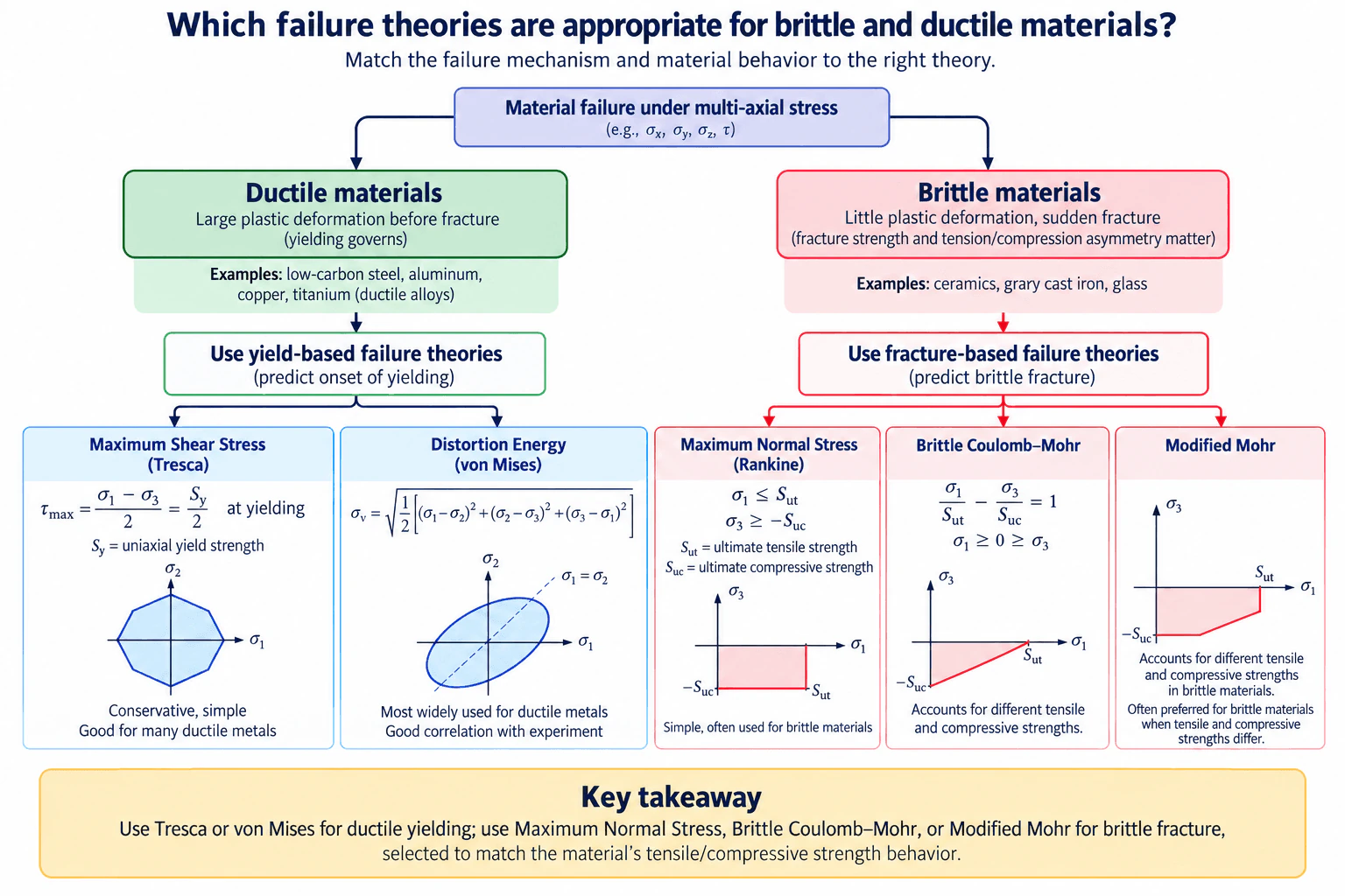
13. Which failure theories are appropriate for brittle and ductile materials?Materials And Material SelectionHard

Question Details

Compare the theories and explain their suitability for each material type.

Short Interview Answer (30-60 seconds)

For ductile materials, use yield-based criteria such as Maximum Shear Stress, or Tresca, and Distortion Energy, or von Mises. Von Mises is widely used for ductile metals, while Tresca is simpler and generally more conservative. For brittle materials, use fracture-based criteria such as Maximum Normal Stress, or Rankine, Brittle Coulomb–Mohr, or Modified Mohr. Rankine is the simplest, while Coulomb–Mohr and Modified Mohr are more suitable when tensile and compressive strengths differ significantly.

Detailed Explanation

The first decision is whether the material is behaving as ductile or brittle under the actual service conditions.

Ductile materials, such as many steels, aluminum alloys, copper, and ductile titanium alloys, usually undergo significant plastic deformation before fracture. Because yielding is normally the governing static failure mode, yield-based failure theories are appropriate.

Let σ1, σ2, and σ3 be the principal stresses ordered so that σ1 ≥ σ2 ≥ σ3, and let Sy be the uniaxial yield strength.

For Maximum Shear Stress theory, or Tresca, yielding begins when the maximum shear stress reaches the shear stress associated with yielding in a uniaxial tensile test:

τmax = (σ1 − σ3) / 2 = Sy / 2 at yielding.

Tresca is simple and conservative for many ductile metals.

For Distortion Energy theory, or von Mises, the equivalent stress is

σv = sqrt{[(σ1 − σ2)^2 + (σ2 − σ3)^2 + (σ3 − σ1)^2] / 2}.

Yielding is predicted when σv reaches Sy. Von Mises generally correlates well with yielding of ductile metals and is widely used in engineering analysis.

Brittle materials, such as ceramics, gray cast iron, and glass, can fracture with little plastic deformation. Their tensile and compressive strengths may differ significantly, so fracture-based criteria are more appropriate.

Let Sut be the ultimate tensile strength and Suc be the positive magnitude of the ultimate compressive strength.

Maximum Normal Stress theory, or Rankine, compares the extreme principal stresses directly with the corresponding strengths. A simple no-failure condition is

σ1 ≤ Sut

and

σ3 ≥ −Suc.

This approach is easy to apply, but it does not model interaction between simultaneous tensile and compressive principal stresses.

Brittle Coulomb–Mohr accounts for unequal tensile and compressive strengths. For a mixed-sign stress state with σ1 ≥ 0 ≥ σ3, the failure boundary is

σ1 / Sut − σ3 / Suc = 1.

Because σ3 is negative in compression, the second term contributes positively to the failure measure. This makes the theory useful when brittle tensile and compressive strengths are substantially different.

Modified Mohr also accounts for different tensile and compressive strengths, but it uses a piecewise failure envelope instead of the single straight mixed tension-compression boundary used by Brittle Coulomb–Mohr. This gives a refined representation of brittle-material behavior across different principal-stress combinations and is often preferred when tension/compression asymmetry is important.

The practical selection is therefore: use Tresca or von Mises for ductile yielding; use Maximum Normal Stress, Brittle Coulomb–Mohr, or Modified Mohr for brittle fracture, selected according to the material's tensile and compressive strength behavior.

Useful Questions to Ask the Interviewer
  • Is the material expected to behave as ductile or brittle at the actual service temperature and environment?
  • Are Sy, Sut, and Suc available for the specified alloy, material condition, and heat treatment?
  • Is the loading static, or could fatigue, creep, impact, or crack growth govern instead?
  • Are the stresses already available as ordered principal stresses, or must they be calculated from the complete stress state?
  • Does an applicable design standard or internal engineering requirement specify a particular failure criterion?
Which failure theories are appropriate for brittle and ductile materials? diagram
How to Explain It in an Interview

I would start with the material's failure mechanism rather than choosing an equation first. If the material undergoes significant plastic deformation before fracture, I would treat it as ductile and check yielding using von Mises or Tresca. Von Mises is usually my general-purpose choice for ductile metals, while Tresca is useful when a simpler and somewhat more conservative criterion is desired.

If the material fractures with little plastic deformation, I would treat it as brittle and use a fracture criterion based on principal stresses and ultimate strengths. Maximum Normal Stress is the simplest option. If the tensile and compressive strengths differ significantly, I would use Brittle Coulomb–Mohr or Modified Mohr because they account for that asymmetry.

I would also verify that the material classification remains valid for the actual temperature, environment, heat treatment, and loading condition. These static theories do not automatically cover fatigue, creep, impact, or fracture-mechanics-controlled crack growth, so I would check whether one of those mechanisms governs before accepting the result.

Technical Approach
  1. Define the loading condition, service temperature, environment, and material condition.
  2. Determine whether the governing behavior is ductile yielding or brittle fracture.
  3. Calculate and order the principal stresses so that σ1 ≥ σ2 ≥ σ3.
  4. For ductile behavior, compare the stress state with Sy using von Mises or Tresca.
  5. For brittle behavior, obtain Sut and Suc and select Maximum Normal Stress, Brittle Coulomb–Mohr, or Modified Mohr according to the importance of tension/compression asymmetry and principal-stress interaction.
  6. Evaluate the selected failure criterion using consistent strength data and sign conventions.
  7. Check whether fatigue, creep, impact, fracture mechanics, temperature effects, environment, or anisotropy fall outside the selected static theory.
  8. Validate the conclusion against traceable material data and any applicable design requirements.
Practical Insights

Von Mises is a strong general-purpose choice for yielding of ductile metals and usually correlates well with observed yielding. Tresca is simpler and generally more conservative, so it may predict yielding earlier. Maximum Normal Stress is simple for brittle materials but does not model interaction between simultaneous tensile and compressive principal stresses. Brittle Coulomb–Mohr and Modified Mohr need both tensile and compressive strength data, but they better represent brittle materials with strong tension/compression asymmetry. None of these static theories automatically covers fatigue, creep, impact, or crack-growth-controlled fracture.

Why Interviewers Ask This

Interviewers want to see whether you can match a material's actual failure mechanism to an appropriate multiaxial failure theory. The key judgment is recognizing that ductile materials are normally checked for yielding, while brittle materials are normally checked for fracture and may have significantly different tensile and compressive strengths.

Common interview mistakes

Common mistakes include using von Mises for a brittle material simply because it is familiar; using ultimate strength instead of yield strength as the ordinary ductile yielding limit; assuming brittle tensile and compressive strengths are equal; using Maximum Normal Stress for a ductile material under significant shear; losing the sign convention for compressive principal stress; failing to order the principal stresses consistently; treating an alloy name as sufficient without checking heat treatment or material condition; and assuming a static failure criterion also covers fatigue, creep, impact, or fracture-mechanics effects.

Interview tip

Lead with the failure mechanism. State that ductile materials are normally governed by yielding, so you use von Mises or Tresca. Brittle materials are normally governed by fracture, so you use Maximum Normal Stress, Brittle Coulomb–Mohr, or Modified Mohr. Then explain that Mohr-based brittle criteria are especially useful when tensile and compressive strengths are significantly different.

Interviewer may ask next
What would you verify before deciding whether to use a ductile or brittle failure theory?

I would verify the material condition and heat treatment, service temperature, environment, expected ductility, yield strength, ultimate tensile strength, ultimate compressive strength where relevant, and whether the loading is truly static. I would also check for fatigue, creep, impact, cracks, anisotropy, or a governing design standard. The same nominal material can behave differently after heat treatment or at a different temperature, so the decision should use traceable data for the actual material condition.

How would your choice change if a brittle material had a much higher compressive strength than tensile strength?

I would favor a criterion that explicitly uses both Sut and Suc rather than relying only on Maximum Normal Stress. Brittle Coulomb–Mohr or Modified Mohr would be more appropriate. For the mixed-sign case σ1 ≥ 0 ≥ σ3, Brittle Coulomb–Mohr uses the interaction σ1/Sut − σ3/Suc = 1. Modified Mohr uses a piecewise envelope and can provide a refined representation of brittle failure when tension/compression asymmetry is important.

14. How do you detect potential problems while developing a new material?Materials And Material SelectionHard

Short Interview Answer (30-60 seconds)

I detect potential problems by defining the material's required performance first, then checking every link between composition, processing, microstructure, properties, manufacturing, environment, and service conditions. I identify likely failure mechanisms such as brittle fracture, fatigue, creep, corrosion, wear, thermal-expansion mismatch, or degradation. Then I use appropriate characterization and representative testing throughout development rather than relying on one final test. I compare results with measurable acceptance criteria and investigate scatter and outliers, because acceptable average properties can still hide local defects, unstable processing, or weak batches.

Detailed Explanation

Developing a new material is not only about achieving high strength, hardness, or temperature resistance. I need to determine whether the material can repeatedly meet all important requirements after realistic processing and throughout its intended service life.

A useful way to organize the problem is through the structure–processing–property relationship:

  • Composition and raw materials influence the phases and microstructure that can form.
  • Processing, such as heat treatment, cooling rate, forming, curing, or consolidation, changes that microstructure.
  • Microstructure controls properties such as yield strength, stiffness, toughness, ductility, hardness, fatigue resistance, creep resistance, and corrosion behavior.
  • Those properties must ultimately satisfy the actual service conditions.

A potential problem can therefore appear anywhere along that chain. For example, a heat treatment may increase strength but reduce toughness, a composite may have excellent properties in one direction but insufficient transverse performance, or two individually corrosion-resistant metals may still create a galvanic-corrosion problem when electrically coupled in a suitable electrolyte.

Useful Questions to Ask the Interviewer
  • What is the intended component and primary function of the material?
  • What loads will it experience: static, cyclic, impact, contact, or combined loading?
  • What operating-temperature range and exposure duration are expected?
  • Will it see water, humidity, salt, chemicals, oxidation, radiation, or another aggressive environment?
  • Which properties are critical: stiffness, yield strength, toughness, hardness, ductility, fatigue life, creep resistance, wear resistance, thermal conductivity, or thermal expansion?
  • Are weight or density important constraints?
  • What manufacturing processes must the material tolerate, such as machining, welding, forming, casting, additive manufacturing, molding, curing, or bonding?
  • Are there mating materials that could create galvanic or thermal-expansion compatibility concerns?
  • What amount of property variation is acceptable between specimens, processing runs, or production batches?
  • Are cost, availability, recyclability, repairability, or end-of-life requirements important?

I would then use the following method.

  1. Convert the application into measurable requirements.

I first translate the service conditions into measurable material requirements instead of using vague targets such as 'strong' or 'heat resistant.' Depending on the application, these might include minimum yield strength, elastic modulus, fracture toughness, allowable density, service-temperature range, corrosion resistance, creep resistance, or a thermal-expansion limit.

I keep different properties separate. High stiffness does not mean high strength, and high strength does not guarantee high toughness. A material can resist elastic deformation well yet still fracture at an unacceptable stress or crack size if its toughness is inadequate.

  1. Identify plausible failure mechanisms early.

I screen the intended operating conditions for mechanisms that could limit the material. Depending on the application, these can include:

  • yielding or excessive deformation,
  • brittle fracture,
  • fatigue cracking under cyclic loading,
  • creep or stress relaxation at elevated temperature,
  • wear or surface damage,
  • general, pitting, crevice, galvanic, or stress-corrosion damage,
  • oxidation or chemical degradation,
  • thermal fatigue or thermal-expansion mismatch,
  • moisture absorption or aging in polymers,
  • delamination or directional weakness in composites,
  • porosity, inclusions, segregation, residual stress, or undesirable phases,
  • degradation caused by welding, forming, machining, curing, or heat treatment.

This failure-mechanism screening determines what evidence I need to collect during development.

  1. Characterize composition and microstructure.

I verify what was actually produced rather than assuming that the nominal chemistry or processing route created the intended structure. Depending on the material, useful characterization can examine chemical composition, phases, grain structure, porosity, inclusions, fiber orientation, interfaces, coating condition, or other relevant microstructural features.

I then connect those observations to measured performance. For example, an unexpected brittle response could be associated with an undesirable phase, excessive grain growth, porosity, contamination, or a processing condition that reduced toughness. The specific cause has to be demonstrated rather than assumed.

  1. Test the properties that control the application.

Testing should correspond to the expected failure mechanisms and service conditions. Mechanical testing may evaluate tensile behavior, hardness, fracture toughness, fatigue, impact response, creep, or wear. Environmental testing may evaluate corrosion, oxidation, chemical exposure, humidity, or thermal cycling.

I would not assume that room-temperature tensile strength represents every service condition. A material intended for elevated-temperature service may require creep and oxidation evaluation, while a material subjected to repeated loads requires appropriate fatigue evaluation.

  1. Evaluate processing sensitivity.

A new material is useful only if its required properties can be produced consistently. I therefore study how realistic variations in processing affect the final material.

For example, when heat treatment is important, changes in temperature, holding time, or cooling history can change phases, grain structure, hardness, strength, ductility, or toughness. The objective is not simply to find one processing condition that creates one good specimen. I want to understand whether there is a sufficiently robust processing window that can consistently produce acceptable material.

Where several development variables interact, a controlled experimental plan can help separate their effects rather than changing many variables simultaneously and losing the cause-and-effect relationship.

  1. Look for anisotropy, local defects, and weak regions.

Average bulk properties can hide serious problems. Rolled materials, composites, and additively manufactured materials can have direction-dependent behavior. Weld regions, interfaces, surfaces, edges, or thick sections may also behave differently from the nominal bulk material.

I therefore consider specimen orientation and sampling location when relevant. If properties vary strongly with direction or location, that variation needs to be characterized and accounted for rather than hidden inside an average value.

  1. Evaluate environmental and material compatibility.

I assess the material in the environment in which it is expected to operate, including compatibility with fluids, coatings, adhesives, fasteners, and neighboring materials.

For dissimilar conductive materials, I consider galvanic compatibility when electrical contact and an electrolyte can exist. For assemblies subjected to temperature changes, I compare thermal expansion because a large mismatch can generate stress, distortion, coating damage, or interface failure even when each individual material has adequate strength.

  1. Examine repeatability and variability.

A single successful specimen does not demonstrate a robust material. I compare multiple specimens and, where appropriate, different processing runs or batches.

I look at both the average performance and the scatter. Large unexplained variation can indicate unstable processing, inconsistent raw material, contamination, local defects, measurement problems, or excessive sensitivity to manufacturing conditions. Outliers should be investigated rather than automatically discarded.

  1. Investigate abnormal results through failure analysis.

If a specimen fails unexpectedly, I preserve the evidence and work backward from the failure. I examine the initiation location, fracture or damage mode, local microstructure, defects, environmental exposure, orientation, and processing history.

The goal is to identify the physical failure mechanism and root cause rather than simply repeating the test until a specimen passes.

  1. Compare alternatives and tradeoffs under equal conditions.

If the new material improves one property but creates another problem, I compare it with suitable alternatives against the same measurable requirements.

For example, titanium may provide attractive specific strength and corrosion resistance in some environments, but cost, availability, manufacturing compatibility, temperature limits, and galvanic interactions still need to be considered. Aluminum, steel, polymers, composites, or ceramics can each offer different combinations of density, stiffness, toughness, corrosion resistance, temperature capability, manufacturability, and recyclability.

The correct material is therefore not simply the one with the highest value of one property. It is the one that best satisfies the complete requirement set with acceptable risk and repeatability.

  1. Validate at increasing levels of realism.

I would normally progress from basic material characterization and coupon testing toward representative processing conditions, environmental exposure, and component-level validation when appropriate. Each stage should address specific risks identified earlier.

I would not claim that a new material is suitable for real equipment solely because a simplified calculation, simulation, or laboratory coupon passes. Final qualification depends on the application, governing requirements, manufacturing route, and appropriate validation evidence.

How to Explain It in an Interview

I would explain that I try to find problems before they become expensive component failures. I start by translating the service conditions into measurable material requirements and identifying the failure mechanisms that could prevent those requirements from being met. Then I examine the complete composition–processing–microstructure–property relationship.

I characterize the material and test it under relevant loading, temperature, and environmental conditions. I also examine manufacturing sensitivity, anisotropy, interfaces, defects, and specimen-to-specimen or batch-to-batch variation because a material that works only in one ideal laboratory sample is not yet robust.

If something fails, I use failure analysis to identify the physical mechanism and determine whether the cause is associated with composition, processing, microstructure, manufacturing, the test itself, or the service condition. I then make a controlled change and repeat the relevant testing. Finally, I move toward increasingly representative validation before concluding that the material is suitable for the intended application.

Technical Approach
  1. Define the intended loads, operating temperature, environment, service life, interfaces, and manufacturing constraints.
  2. Translate those conditions into measurable material-property requirements.
  3. Map composition and processing variables to the expected microstructure and properties.
  4. Screen plausible failure mechanisms such as fracture, fatigue, creep, wear, corrosion, degradation, thermal mismatch, or delamination.
  5. Select characterization methods and tests that directly address those mechanisms.
  6. Produce and evaluate specimens over relevant processing conditions rather than only one nominal condition.
  7. Check microstructure, defects, anisotropy, interfaces, and local property variation.
  8. Evaluate environmental, galvanic, thermal, and manufacturing compatibility.
  9. Measure repeatability and investigate unexpected scatter or outliers.
  10. Perform failure analysis on abnormal specimens and trace the mechanism back to composition, processing, structure, manufacturing, test conditions, or service conditions.
  11. Compare corrective options and alternative materials using the same measurable requirements.
  12. Repeat the relevant tests after changes and progress toward representative component-level validation before qualification.
Practical Insights

The main tradeoff is test coverage versus development time, cost, and available material. Testing every possible combination of composition, processing, temperature, environment, and loading is usually impractical, so the development program should prioritize the conditions and failure mechanisms with the greatest technical risk. Another important tradeoff is peak performance versus robustness: a material with exceptional properties under one tightly controlled condition may be less useful than one with slightly lower properties but a wider and more repeatable processing window. Manufacturing compatibility, availability, corrosion behavior, density, recyclability, and service life also need to be considered alongside mechanical performance.

Why Interviewers Ask This

Interviewers want to see whether I can identify material-development risks systematically instead of waiting for a final test to fail. They are evaluating whether I understand structure–processing–property relationships, likely failure mechanisms, test planning, manufacturing variability, environmental compatibility, and how to use evidence to decide whether a material is ready for further development.

Common interview mistakes

Common mistakes include focusing only on strength while ignoring stiffness or toughness; treating the nominal alloy name as sufficient without considering material condition or heat treatment; testing only at room temperature when actual service conditions differ; overlooking fatigue, creep, corrosion, wear, anisotropy, thermal expansion, or galvanic compatibility; accepting one successful specimen as proof of repeatability; relying only on average values while ignoring scatter and local defects; changing several development variables at once so the root cause becomes unclear; discarding unexplained outliers without investigation; and declaring a material suitable before representative manufacturing and service-condition validation.

Interview tip

Organize the answer around the full chain of service requirements → failure mechanisms → composition and processing → microstructure → properties → validation. Mentioning repeatability, processing sensitivity, and failure analysis makes the answer stronger because it shows that material development is not just about achieving target properties once; it is about understanding why the material behaves as it does, detecting weaknesses early, and showing that acceptable behavior is repeatable.

Interviewer may ask next
How would you determine whether an unexpected material failure came from the material itself or from the manufacturing process?

I would first verify the test setup and preserve the failed specimen. Then I would compare its composition, microstructure, defect population, fracture or damage location, orientation, and processing history with specimens that performed normally. If failures correlate with features such as porosity, residual stress, an undesirable phase, excessive grain growth, poor bonding, contamination, or a particular heat-treatment condition, that would provide evidence of a processing-related cause. I would then change one controlled variable at a time and repeat the relevant characterization and testing. The objective is to establish a repeatable cause-and-effect relationship rather than assuming that either the nominal material chemistry or the manufacturing process is responsible.

What would change if the new material had to operate at a much higher temperature?

I would add temperature-dependent properties and high-temperature failure mechanisms to the requirements. Room-temperature yield strength alone would no longer be sufficient. I would consider creep, stress relaxation, oxidation, phase stability, thermal expansion, thermal cycling, and possible loss of strength, ductility, or toughness after prolonged exposure. I would also check whether coatings, joints, and neighboring materials remain compatible at the higher temperature. Testing and characterization would therefore need to reproduce the relevant temperature and exposure duration, and alternative materials would need to be compared using those same high-temperature requirements.

15. Why does a bicycle pump warm up during use?Thermodynamics And Heat TransferEasy

Short Interview Answer (30-60 seconds)

A bicycle pump warms because mechanical work is converted into thermal energy during pumping. When the piston rapidly compresses the trapped air, work done on the gas increases its internal energy and therefore its temperature. The compression is approximately adiabatic over a short stroke because there is little time for heat transfer. The hotter compressed air then transfers some energy to the pump walls. Friction at the piston and seals also generates heat, so both compression heating and mechanical friction can contribute to the warm pump.

Detailed Explanation

When the piston of a bicycle pump moves through a compression stroke, it does mechanical work on the air trapped inside the cylinder. The air is forced into a smaller volume while its pressure rises. According to the first law of thermodynamics, this work input can increase the internal energy of the gas.

Using the air in the pump cylinder as a temporary closed-system model during the compression portion of a stroke, and defining Q as heat transferred into the air and W_in as work done on the air, the energy balance is:

ΔU = Q + W_in

For a rapid compression stroke, there is relatively little time for heat transfer through the cylinder wall. A useful first approximation is therefore:

Q ≈ 0

so:

ΔU ≈ W_in > 0

The internal energy of the air increases, which causes its temperature to rise.

For an ideal gas undergoing approximately reversible adiabatic compression, the temperature-volume relationship is:

T₂/T₁ = (V₁/V₂)^(γ - 1)

where T₁ and T₂ are absolute temperatures in kelvin, V₁ and V₂ are the initial and final gas volumes, and γ is the ratio of specific heats. Because the air is compressed so that V₂ < V₁, this idealized relation predicts T₂ > T₁.

The real bicycle-pump process is transient and is not perfectly adiabatic or reversible. Some energy is transferred from the hotter compressed air to the inner cylinder wall by convection and then through the pump material by conduction. Repeated strokes can therefore raise the temperature of the pump body. Some energy also leaves with the compressed air as it flows into the tire.

Mechanical friction provides another source of heating. The piston seal rubs against the cylinder wall, and other moving interfaces may dissipate mechanical energy as heat. The relative importance of compression heating and friction depends on the pump design, pumping speed, pressure, seal forces, materials, and cooling conditions.

After pumping stops, the pump cools toward ambient temperature as energy is transferred to its surroundings, mainly by convection and also by radiation.

Useful Questions to Ask the Interviewer
  • Are we expected to explain only the thermodynamic compression effect, or should we also include seal and piston friction?
  • Should the compression stroke be approximated as adiabatic, or should heat transfer during the stroke be considered explicitly?
  • Are we discussing the temperature rise of the compressed air, the pump body, or both?

For a typical conceptual interview answer, I would assume rapid transient compression, approximately ideal-gas behavior, and limited heat transfer during each individual compression stroke. Under those assumptions, work done on the air raises its temperature, and some of that energy is subsequently transferred to the pump body.

A useful limiting-case check is pumping speed. If the air were compressed much more slowly, it would have more time to transfer energy to the surroundings during compression. The process would move closer to isothermal compression, so the peak gas-temperature rise would be smaller than for a rapid, nearly adiabatic stroke.

How to Explain It in an Interview

I would say that pushing the piston requires mechanical work. Part of that work compresses the trapped air, raising its internal energy and temperature. Because each compression stroke happens quickly, there is little time for heat to escape, so the compression can be approximated as adiabatic. The hotter air transfers some energy to the cylinder, while friction at the piston and seals adds additional heating. Repeated strokes make the pump noticeably warm. Slower pumping allows more heat transfer during compression and generally reduces the peak temperature rise of the air.

Technical Approach
  1. Define the system as the air temporarily trapped in the pump cylinder during the compression portion of a stroke.
  2. Recognize that the process is transient rather than steady state.
  3. Apply the first law using a clear sign convention: work done on the air increases its internal energy unless that energy is removed as heat.
  4. For a rapid stroke, approximate heat transfer during compression as small, making the process approximately adiabatic.
  5. Conclude that decreasing gas volume while performing work on the gas raises its temperature.
  6. Account for subsequent heat transfer from the hotter compressed air to the pump wall.
  7. Include piston and seal friction as an additional source of heating.
  8. Check the limiting case: slower compression allows more heat transfer and moves the process closer to isothermal behavior, reducing the peak gas-temperature rise.
Practical Insights

The main physical tradeoff is compression rate versus heat-transfer time. Rapid compression gives the air less time to reject energy during the stroke, so its temperature can rise more. Slower compression permits more heat transfer while the gas is being compressed and reduces the peak temperature rise. The observed pump temperature also depends on compression ratio, pressure, pumping rate, cylinder material, surface area, seal friction, airflow around the pump, and cooling time between strokes.

Why Interviewers Ask This

Interviewers are checking whether the candidate can connect a familiar observation to the first law of thermodynamics, recognize rapid gas compression as approximately adiabatic, distinguish the temperature rise of the compressed air from heat transfer to the pump body, and recognize mechanical friction as an additional source of heating.

Common interview mistakes

A common mistake is attributing all of the warming to friction and ignoring the temperature rise caused by gas compression. Another mistake is saying that pressure by itself creates heat without identifying the mechanical work that increases the gas's internal energy. It is also incorrect to describe the real pump as perfectly adiabatic; adiabatic compression is an approximation for a sufficiently rapid stroke because some heat transfer still occurs. Another mistake is treating repeated pumping as immediately steady state even though the temperatures of the gas and pump body change with time.

Interview tip

Start with the first law: the piston does work on the trapped air, which raises the air's internal energy and temperature. Then explain that a rapid stroke is approximately adiabatic, mention heat transfer from the hot air to the cylinder, and add piston-seal friction as another source of heating. That gives a complete answer without overcomplicating the basic physics.

Interviewer may ask next
How could you test whether gas compression is contributing significantly to the pump's temperature rise?

Compare tests that produce different amounts of gas compression while keeping other conditions as similar as practical. Measure temperatures near the compression chamber and near the sliding seal, and control variables such as ambient temperature, pumping rate, number of strokes, initial pump temperature, and cooling time. A substantially greater temperature rise near the compression region when the pump is working against higher pressure would support a significant compression-heating contribution. Temperature measurements alone may not perfectly separate compression from friction, so the test design should also consider seal heating and heat conduction through the pump.

What would change if the bicycle pump were operated much more slowly?

Slower compression gives the air more time to transfer energy through the pump wall while its volume is decreasing. The gas process therefore moves away from the adiabatic limit and closer to isothermal behavior. The peak compressed-air temperature would generally be lower. The final pump-body temperature would still depend on total work input, pumping duration, friction, heat losses, and cooling to the surroundings.

16. How do conduction, convection, and radiation differ?Thermodynamics And Heat TransferEasy

Short Interview Answer (30-60 seconds)

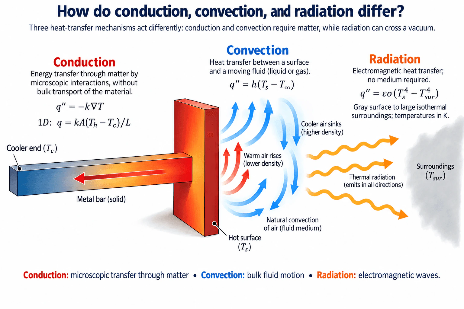
Conduction transfers thermal energy through matter by microscopic interactions without bulk transport of the material. Convection transfers heat between a surface and a moving fluid, so fluid motion carries energy away from or toward the surface. Radiation transfers thermal energy by electromagnetic waves and does not require a material medium, so it can cross a vacuum. Common engineering relations are Fourier’s law for conduction, q'' = h(T_s - T_∞) for convection, and q'' = εσ(T_s^4 - T_sur^4) for gray-surface radiation to large isothermal surroundings.

Detailed Explanation

Conduction, convection, and radiation differ mainly in how thermal energy is transported. For all three mechanisms, the net heat transfer is from a higher-temperature region toward a lower-temperature region.

Conduction is energy transfer through matter by microscopic interactions, without bulk transport of the material. In a solid, energy can be transferred through lattice vibrations and, in conductive materials, free electrons. In fluids, molecular interactions also conduct heat. Fourier’s law is

q'' = -k∇T

where q'' is conductive heat flux in W/m², k is thermal conductivity in W/(m·K), and ∇T is the temperature gradient in K/m. The negative sign means heat flux points toward decreasing temperature. For steady one-dimensional conduction through a uniform section with constant k, cross-sectional area A, length L, and no internal heat generation,

q = kA(T_h - T_c)/L

where q is heat-transfer rate in W, T_h is the hot-side temperature, and T_c is the cooler-side temperature. This matches the diagram’s metal bar, where the end attached to the hot surface is hottest and heat conducts toward the cooler free end.

Convection is heat transfer between a surface and a moving fluid such as air or water. A common surface relation is

q'' = h(T_s - T_∞)

where h is the convective heat-transfer coefficient in W/(m²·K), T_s is the surface temperature, and T_∞ is the bulk-fluid temperature. In the diagram, natural convection occurs next to the hot surface: warmer air becomes less dense and rises, while cooler, denser air sinks, creating circulation. Convection therefore involves both energy transfer at the surface and bulk motion of the fluid.

Radiation is thermal energy transfer by electromagnetic waves. It does not require matter, so it can occur through a vacuum. For a gray surface exchanging radiation with large isothermal surroundings, the net radiative heat flux is

q'' = εσ(T_s^4 - T_sur^4)

where ε is surface emissivity, σ is the Stefan–Boltzmann constant, T_s is the absolute surface temperature, and T_sur is the absolute surroundings temperature. Temperatures in this fourth-power relation must be in kelvin. The diagram shows radiation leaving the hot surface toward cooler surroundings.

The simplest comparison is: conduction is microscopic transfer through matter, convection involves bulk fluid motion, and radiation uses electromagnetic waves. In real thermal systems, all three mechanisms can act at the same time.

Useful Questions to Ask the Interviewer
  • Are you looking for a conceptual comparison only, or should I include the governing equations?
  • Should I assume steady-state conditions and constant properties for the conduction example?
  • For convection, should I discuss natural convection, forced convection, or both?
  • For radiation, may I assume a gray surface exchanging with large isothermal surroundings?
How do conduction, convection, and radiation differ? diagram
How to Explain It in an Interview

Start with the physical mechanism. Say that conduction transfers energy through matter without bulk transport of the material, convection transfers heat between a surface and a moving fluid, and radiation transfers energy by electromagnetic waves and does not require a medium. Then support each mechanism with one governing relation: Fourier’s law for conduction, q'' = h(T_s - T_∞) for convection, and q'' = εσ(T_s^4 - T_sur^4) for gray-surface radiation to large surroundings. State that the radiation temperatures are absolute temperatures. Finish by noting that multiple heat-transfer modes commonly occur simultaneously.

Technical Approach
  1. Define the thermal system and identify the hotter and cooler regions.
  2. Use the sign convention that positive heat transfer follows the chosen heat-flow direction, and verify that net heat flows from hot to cold.
  3. Identify the physical transport mechanism: microscopic transfer through matter, surface-to-fluid transfer with bulk fluid motion, or electromagnetic radiation.
  4. For conduction, use Fourier’s law and state the geometry, dimensionality, material-property, and steady-state assumptions before using a simplified one-dimensional expression.
  5. For convection, identify T_s, T_∞, the fluid, and whether the motion is natural or forced before selecting an appropriate value or correlation for h.
  6. For radiation, use absolute temperatures and state the surface and surroundings assumptions before applying the Stefan–Boltzmann relation.
  7. Check units, heat-flow direction, and physical plausibility.
  8. In a real system, determine whether conduction, convection, and radiation act simultaneously rather than assuming only one mode is present.
Practical Insights

Conduction depends on thermal conductivity, geometry, and temperature gradient. Convection depends on fluid properties, geometry, flow conditions, and the convective heat-transfer coefficient; natural convection is driven by buoyancy, while forced convection is driven by a fan, pump, or other imposed flow. Radiation depends strongly on absolute temperature because of the fourth-power temperature relation, and it also depends on emissivity and the radiative surroundings. The dominant mechanism can change as temperature, airflow, material, surface condition, or geometry changes.

Why Interviewers Ask This

Interviewers want to see whether you can distinguish the three fundamental heat-transfer mechanisms, identify the physical process and medium involved, choose an appropriate governing relation, state its assumptions, and reason correctly about the direction of heat transfer.

Common interview mistakes

Common mistakes include saying conduction occurs only in solids, describing convection as only fluid motion without recognizing heat transfer between the surface and fluid, claiming radiation requires air or another material medium, using Celsius instead of absolute temperature in a T^4 radiation relation, reversing the heat-flow direction in Fourier’s law, and using simplified equations without stating their assumptions.

Interview tip

Lead with one sentence for each physical mechanism, then give the governing equation and its main assumption. A strong answer also mentions that conduction, convection, and radiation can occur simultaneously and that radiation calculations involving T^4 require absolute temperature.

Interviewer may ask next
What assumptions should you check before using the simple conduction, convection, and radiation equations?

For q = kA(T_h - T_c)/L, check that conduction is effectively one-dimensional, the section is uniform, k is appropriately treated as constant or averaged, the condition is steady, and internal heat generation is negligible or handled separately. For q'' = h(T_s - T_∞), define the surface and bulk-fluid temperatures and use an h value or correlation appropriate to the fluid, geometry, flow regime, and natural or forced convection condition. For q'' = εσ(T_s^4 - T_sur^4), use absolute temperatures and verify that the gray-surface and large-isothermal-surroundings assumptions are reasonable.

How would the heat-transfer mechanisms change if the surrounding air were removed and the component were placed in a vacuum?

Convection would disappear because there would be no surrounding fluid to circulate. Conduction could still occur through solid contacts, supports, or other material connections. Radiation would continue across the vacuum because electromagnetic waves do not require a material medium. The thermal behavior would therefore be controlled mainly by the remaining solid-conduction paths and radiation.

17. Does adding heat to a system always increase its internal energy?Thermodynamics And Heat TransferEasy

Short Interview Answer (30-60 seconds)

No. Adding heat to a system does not always increase its internal energy. For a closed system, if heat transferred into the system is positive and work done by the system is positive, the first law is ΔU = Q - W when kinetic and potential energy changes are negligible. Internal energy increases only when the heat added exceeds the work done by the system. For example, during an isothermal expansion of an ideal gas, heat can enter while the gas performs an equal amount of work, giving ΔU = 0.

Detailed Explanation

Heat and internal energy are different concepts. Heat, Q, is energy transferred across a system boundary because of a temperature difference. Internal energy, U, is a thermodynamic property representing microscopic energy stored within the system.

For a closed system, assume that changes in kinetic and potential energy are negligible. Using the sign convention that heat transferred into the system is positive and work done by the system is positive, the first law becomes:

ΔU = Q - W

where:

  • ΔU = change in internal energy, in joules
  • Q = heat transferred into the system, in joules
  • W = work done by the system on its surroundings, in joules

Therefore, Q > 0 only tells us that heat enters the system. Whether internal energy increases depends on both Q and W.

If no work is done, such as when heating a rigid closed vessel and neglecting other work modes, W = 0. Then:

ΔU = Q

so the added heat increases the system's internal energy.

If the system expands and performs work, part or all of the incoming heat can be transferred back out as work. If W = Q, then:

ΔU = 0

A common example is an ideal gas undergoing isothermal expansion. For an ideal gas, internal energy depends only on temperature. If its temperature remains constant, ΔU = 0. The first law then requires Q = W, so the heat entering the gas is balanced by the work the gas performs during expansion.

It is also possible for internal energy to decrease while heat is entering. If W > Q, then Q - W < 0 and therefore ΔU < 0. In that case, the system performs enough work that some of its stored internal energy is also used.

Phase change provides another useful distinction between heat addition and temperature rise. During processes such as boiling or melting at approximately constant pressure, heat can be added while temperature remains nearly constant. The transferred energy contributes to the phase change, and the system's internal energy can still increase even though its temperature does not rise significantly.

The correct conclusion must therefore come from the complete energy balance for the defined system boundary rather than from heat transfer alone.

Useful Questions to Ask the Interviewer
  • Are we considering a closed system or a control volume with mass flow?
  • Can changes in kinetic and potential energy be neglected?
  • What sign convention should be used for heat and work?
  • Is the process constant-volume, constant-pressure, isothermal, adiabatic, or otherwise specified?
  • Are there other work modes or a phase change that must be included in the energy balance?
How to Explain It in an Interview

Start by defining the system and sign convention. For a closed system with negligible kinetic and potential energy changes, write ΔU = Q - W. Explain that Q > 0 only means heat enters the system; it does not by itself determine the sign of ΔU. Then contrast two cases. In a rigid closed vessel with no other work modes, W = 0, so added heat increases internal energy. In an isothermal expansion of an ideal gas, ΔU = 0 and the incoming heat is balanced by expansion work, so Q = W. Conclude that internal-energy change must be determined from the complete first-law energy balance.

Technical Approach
  1. Define the system boundary and identify whether the problem concerns a closed system or a control volume.
  2. State the sign convention for heat and work.
  3. Identify whether changes in kinetic and potential energy are important.
  4. For a closed system with negligible kinetic and potential energy changes, apply ΔU = Q - W.
  5. Identify all relevant work modes rather than assuming only boundary work.
  6. Compare the heat entering the system with the work leaving the system.
  7. If Q > W, internal energy increases; if Q = W, internal energy remains unchanged; if Q < W, internal energy decreases.
  8. Check that the result is consistent with process constraints such as constant volume, constant temperature, or phase change.
Practical Insights

The main physical tradeoff is how incoming energy is divided between energy stored in the system and energy leaving as work. In a rigid closed vessel with no other work modes, heat addition is directly reflected in internal-energy increase. In an expanding system, some or all of the heat may support expansion work. Real systems may also involve shaft work, electrical work, kinetic-energy changes, potential-energy changes, heat losses, mass flow, or phase change, so the complete energy balance must match the actual system boundary and operating conditions.

Why Interviewers Ask This

Interviewers ask this to check whether a candidate understands the first law of thermodynamics and can distinguish heat transfer from a change in internal energy. The key judgment is recognizing that energy entering as heat may also leave the system as work, so heat added to a system does not automatically equal its increase in internal energy.

Common interview mistakes

Common mistakes include assuming that adding heat always increases temperature or internal energy, confusing heat with internal energy, ignoring work in the first-law balance, and using an inconsistent sign convention. Another mistake is assuming that constant temperature means no heat transfer. For an ideal gas undergoing isothermal expansion, heat can enter while temperature and internal energy remain constant because the incoming energy is transferred out as work.

Interview tip

State the first law early and define the sign convention: ΔU = Q - W for a closed system when changes in kinetic and potential energy are negligible. Then give two contrasting examples: heating a rigid vessel gives W = 0 and ΔU > 0, while isothermal expansion of an ideal gas can give Q = W and ΔU = 0. This directly demonstrates why heat addition alone does not determine the internal-energy change.

Interviewer may ask next
If heat is added to a gas in a rigid, closed container, what happens to its internal energy?

If the container is rigid, there is no boundary expansion work. Assuming there are no other work modes and changes in kinetic and potential energy are negligible, W = 0. The first law becomes ΔU = Q. Therefore, positive heat transfer into the gas increases its internal energy. For an ideal gas, the increase in internal energy also corresponds to an increase in temperature.

Can a system receive heat while its internal energy decreases?

Yes. Using the sign convention ΔU = Q - W, a system can receive heat so that Q > 0 but still have ΔU < 0 if it performs more work than the heat it receives, meaning W > Q. The additional energy required for that work comes from the system's stored internal energy. The conclusion must be based on the complete energy balance for the defined system boundary.

18. Can heat enter or leave a body while its temperature stays constant?Thermodynamics And Heat TransferMedium

Question Details

Give examples that support your explanation.

Short Interview Answer (30-60 seconds)

Yes. Heat can enter or leave a body while its temperature stays constant. The clearest example is a phase change. At approximately constant pressure, ice at its melting point can absorb heat and melt while remaining near 0 °C, and saturated steam can release heat and condense while remaining at its saturation temperature. The transferred energy changes the phase rather than producing a sensible temperature change. Heat transfer can also occur during an isothermal process, such as an ideal gas absorbing heat while doing an equal amount of work.

Detailed Explanation

Yes. Heat is energy transferred across a system boundary because of a temperature difference, while temperature is a thermodynamic property of the body. Therefore, heat can enter or leave a body without requiring its temperature to change.

A common example is a phase change of a pure substance under approximately constant pressure. During melting, boiling, condensation, or freezing, heat can cross the boundary while the substance remains at approximately its saturation or phase-change temperature. The transferred energy is associated with changing phase rather than producing sensible heating or cooling.

For a closed system with negligible changes in kinetic and potential energy, using the sign convention that heat entering the system is positive and work done by the system is positive, the first law is

Q - W = ΔU

where Q is net heat added to the system, W is work done by the system, and ΔU is the change in internal energy.

Constant temperature does not automatically mean ΔU = 0. During a phase change, the internal energy can change even though the temperature remains essentially constant.

For example, consider ice at its melting point at approximately atmospheric pressure. If heat is supplied, the ice melts while the ice-water mixture remains near 0 °C until the phase change is complete. For a phase change represented by an appropriate latent heat L, the heat transfer can be written as

Q = mL

where m is the mass undergoing the phase change and L is the latent heat for that transition under the stated conditions.

Boiling provides another example. Liquid water at its saturation temperature can absorb heat and become vapor while its saturation temperature remains essentially constant if the pressure remains constant. Conversely, saturated vapor can reject heat during condensation while remaining at approximately the same saturation temperature.

Heat transfer at constant temperature is not limited to phase changes. Consider a single-phase ideal gas undergoing an isothermal process. For an ideal gas, internal energy depends only on temperature. If temperature is constant, then ΔU = 0. From the first law,

Q = W

so the gas can absorb heat while doing an equal amount of boundary work, or reject heat while work is done on it, depending on the process direction and sign convention.

Useful Questions to Ask the Interviewer
  • Are we considering a closed system or a control volume?
  • Is the substance undergoing a phase change or remaining in one phase?
  • Is pressure approximately constant during the process?
  • Should kinetic and potential energy changes be neglected?
  • Are we assuming equilibrium or a quasi-equilibrium process so that the body has a meaningful uniform temperature?
How to Explain It in an Interview

I would first separate heat from temperature. Heat is energy crossing the system boundary, while temperature describes the thermal state of the material. Therefore, heat transfer does not necessarily require a temperature change.

I would then use melting as the simplest example. Ice at its melting point can absorb heat and change from solid to liquid while remaining near the same temperature. The added energy supports the phase change rather than raising the temperature.

I would support this with the first law, Q - W = ΔU. During a phase change, internal energy can change even while temperature remains constant. As a second example, an ideal gas can undergo an isothermal process in which ΔU = 0 and the heat entering the gas is balanced by work leaving the gas.

The key conclusion is that constant temperature does not mean zero heat transfer. The effect of the transferred heat depends on the material state, phase behavior, work interactions, pressure, and other operating conditions.

Technical Approach
  1. Define the system boundary and state the heat and work sign convention.
  2. Determine whether the process involves a phase change or remains within a single phase.
  3. Identify important constraints such as constant pressure, constant temperature, or prescribed work interaction.
  4. Apply the first-law energy balance, neglecting kinetic and potential energy changes only when justified.
  5. For a phase change, use an appropriate phase-change energy relation such as Q = mL when the applicable latent heat is known and the assumptions support it.
  6. For a single-phase isothermal process, determine how heat transfer is balanced by work or other energy interactions.
  7. Check that the assumed state, pressure, temperature, and direction of heat transfer are physically consistent.
Practical Insights

The main engineering issue is determining where the transferred energy goes. During ordinary sensible heating or cooling, heat usually changes temperature. During a phase change, substantial energy can be transferred while temperature changes little or not at all under equilibrium conditions. In an isothermal single-phase process, heat transfer may be balanced by work. Real systems can have pressure changes, temperature gradients, heat losses, and non-equilibrium effects, so perfectly constant temperature is often an idealization.

Why Interviewers Ask This

Interviewers want to see whether the candidate understands that heat transfer and temperature change are not the same thing. The key judgment is recognizing that energy can cross a system boundary as heat while the temperature remains constant, particularly during a phase change or when another energy interaction, such as work, balances the heat transfer.

Common interview mistakes

Common mistakes include saying that heat transfer must always change temperature, assuming that constant temperature always means constant internal energy, and confusing heat with temperature. Another mistake is applying Q = mcΔT during a phase change when a latent-heat relation is the more appropriate model. It is also important not to ignore pressure or work interactions because they can determine whether a constant-temperature process is physically possible.

Interview tip

Start with the direct answer and a simple phase-change example: ice can absorb heat while melting near 0 °C at atmospheric pressure. Then use the first law to explain why. Adding an isothermal ideal-gas example shows that constant-temperature heat transfer is not limited to phase changes.

Interviewer may ask next
If the temperature remains constant, does that always mean the internal energy remains constant?

No. The relationship depends on the substance and its state. For a single-phase ideal gas, internal energy depends only on temperature, so constant temperature gives ΔU = 0. During a phase change, however, internal energy can change substantially while temperature remains approximately constant. The material model and phase must therefore be identified before drawing a conclusion about internal energy.

What happens if heat continues to enter after all of the ice has melted?

Once the phase change is complete, continued heat input will normally raise the liquid-water temperature if there is no compensating work or other energy transfer. For a simple single-phase approximation with nearly constant specific heat, the sensible heat can be estimated using Q = mcΔT. The constant-temperature behavior therefore lasts only while the conditions supporting the phase change or another balancing energy interaction remain present.

19. Where does the energy for work come from during an isothermal expansion of an ideal gas?Thermodynamics And Heat TransferMedium

Short Interview Answer (30-60 seconds)

During an isothermal expansion of an ideal gas, the gas does boundary work while its temperature remains constant. For an ideal gas, internal energy depends only on temperature, so the change in internal energy is zero. From the first law, the heat transferred into the gas must therefore equal the work done by the gas. The energy for the work comes from heat supplied by the surroundings, not from a decrease in the gas's internal energy.

Detailed Explanation

Consider a fixed mass of ideal gas in a piston-cylinder undergoing an isothermal expansion. Define the gas as the closed system. Use the sign convention that heat transferred into the gas is positive and work done by the gas on the surroundings is positive.

For a closed system with negligible changes in kinetic and potential energy, the first law is

ΔU = Q - W

where ΔU is the change in internal energy, Q is the net heat transferred into the gas, and W is the net work done by the gas.

For an ideal gas, internal energy is a function of temperature only. Because the process is isothermal,

T₂ = T₁

so

ΔU = 0.

The first-law balance therefore becomes

0 = Q - W

and hence

Q = W.

Therefore, the energy used to perform expansion work is supplied as heat through the system boundary. Heat enters the gas from a thermal reservoir or other surroundings while an equal amount of energy, on a net basis, leaves as work. The heat input prevents the gas's internal energy and temperature from decreasing while it performs work.

If the expansion is reversible or quasi-static, the pressure of the ideal gas can be written as

P = nRT/V.

The boundary work is then

W = ∫₍V₁₎⁽V₂⁾ P dV = nRT ln(V₂/V₁).

Because ΔU = 0,

Q = W = nRT ln(V₂/V₁).

Here, n is the amount of gas in moles, R is the universal gas constant, T is the constant absolute temperature in kelvin, and V₁ and V₂ are the initial and final volumes. For an expansion, V₂ > V₁, so W is positive and an equal positive net heat transfer into the gas is required under the stated sign convention.

The reversible logarithmic expression should not be applied automatically to every isothermal expansion. For an irreversible process, the actual work depends on the external pressure and the actual path. However, for a closed ideal-gas system that remains at the same temperature and has negligible kinetic and potential energy changes, ΔU = 0 still gives Q = W for the actual process.

A physical heat-transfer mechanism must also exist for the process to remain isothermal while the gas performs work. In the reversible limit, heat transfer occurs through an infinitesimal temperature difference. In a real process, a finite temperature difference may be needed to transfer heat at a finite rate, and sufficiently slow expansion together with effective thermal contact can help keep the gas temperature approximately uniform and constant.

Useful Questions to Ask the Interviewer
  • Are we assuming an ideal gas throughout the process?
  • Is the expansion reversible or quasi-static, or are we only being asked about the energy balance?
  • Are changes in kinetic and potential energy negligible?
  • Is the gas in thermal contact with a reservoir that maintains approximately constant temperature?

These assumptions matter because Q = W follows from ΔU = 0 for the ideal gas under the stated energy balance, while W = nRT ln(V₂/V₁) additionally requires a reversible or quasi-static isothermal path.

How to Explain It in an Interview

Start with the key ideal-gas property: internal energy depends only on temperature. Since the expansion is isothermal, the temperature does not change, so ΔU = 0. Then apply the first law, ΔU = Q - W. Setting ΔU to zero gives Q = W. Therefore, the gas can perform work because heat entering from the surroundings replaces the energy leaving as work. If the expansion is reversible, the work can be calculated as nRT ln(V₂/V₁). Finish with the physical check: if heat were not supplied and the gas still performed expansion work, its internal energy would generally decrease and an ideal gas would cool rather than remain isothermal.

Technical Approach

1. Define the system as the fixed mass of ideal gas and state the sign convention: heat into the gas is positive and work done by the gas is positive. 2. Neglect kinetic and potential energy changes unless the problem states otherwise. 3. Identify the process as isothermal, so T₂ = T₁. 4. Use the ideal-gas property that internal energy depends only on temperature, giving ΔU = 0. 5. Apply the closed-system first law, ΔU = Q - W. 6. Substitute ΔU = 0 to obtain Q = W. 7. Conclude that heat entering through the system boundary supplies the energy that leaves as expansion work. 8. If the process is reversible or quasi-static and a numerical value is required, evaluate W = nRT ln(V₂/V₁), using absolute temperature and consistent units. 9. Check the result physically: for V₂ > V₁, reversible expansion work is positive and an equal positive heat input is required under the stated sign convention.

Practical Insights

The main physical issue is maintaining constant temperature while the gas expands. As energy leaves as work, an equal amount of net heat must enter so that the ideal gas's internal energy remains unchanged. A rapid real expansion may not allow enough heat transfer to keep the temperature uniform and constant, so an isothermal model is often most appropriate when thermal contact is effective and the process is sufficiently slow. The logarithmic work expression has an additional limitation: it applies to a reversible or quasi-static ideal-gas path. For an irreversible isothermal expansion, the first-law conclusion Q = W still applies when ΔU = 0, but the work must be determined from the actual external-pressure path.

Why Interviewers Ask This

This question tests whether the candidate can apply the first law of thermodynamics correctly, distinguish heat transfer from work, and recognize that the internal energy of an ideal gas depends only on temperature. It also checks whether the candidate understands the system boundary and can explain why constant temperature does not mean that no energy is transferred.

Common interview mistakes

A common mistake is saying that the expansion work comes from a decrease in the gas's internal energy. For an ideal gas undergoing an isothermal process, ΔU = 0, so there is no net decrease in internal energy. Another mistake is assuming that constant temperature means Q = 0; here, heat transfer is what supplies the energy needed for the work while maintaining constant temperature. Candidates may also incorrectly use W = PΔV when pressure changes during the process, or use W = nRT ln(V₂/V₁) without stating the reversible or quasi-static assumption.

Interview tip

Lead with the first-law argument: for an ideal gas, isothermal means ΔU = 0, so Q = W under the stated sign convention. Then explain physically that heat entering from the surroundings replaces the energy leaving as expansion work. Mention W = nRT ln(V₂/V₁) only when the expansion is reversible or quasi-static and the interviewer wants the work calculation.

Interviewer may ask next
Would Q = W still be true if the isothermal expansion were irreversible?

Yes, provided the system is a closed ideal gas, its initial and final temperatures are equal, and changes in kinetic and potential energy are negligible. Because ideal-gas internal energy depends only on temperature, ΔU = 0. The first law then gives Q = W for the actual process under the stated sign convention. However, the reversible expression W = nRT ln(V₂/V₁) generally cannot be used. For an irreversible piston-cylinder expansion, the boundary work is determined from the actual external pressure, such as W = ∫ P_ext dV when that description is applicable.

What happens if the gas expands while no heat enters from the surroundings?

If Q = 0 and the gas performs positive work, the first law gives ΔU = -W, assuming negligible kinetic and potential energy changes. The gas therefore loses internal energy. For an ideal gas, internal energy depends only on temperature, so its temperature decreases. Thus an expansion with no heat transfer is adiabatic rather than isothermal unless some other energy-transfer mechanism compensates for the work.

20. How would you address the difficulties of removing waste heat from high-power systems?Thermodynamics And Heat TransferHard

Short Interview Answer (30-60 seconds)

I would start by defining the system boundary and calculating the continuous and transient waste-heat loads. Then I would work backward from the maximum allowable component temperature and worst-case sink temperature to establish the allowable total thermal resistance. I would break the heat path into conduction, interfaces, convection, heat-exchanger resistance, and radiation where significant, then identify the dominant bottleneck. For high heat fluxes, I might progress from improved heat spreading and forced air to liquid or two-phase cooling, and use refrigeration only if the required temperature is below what the available heat sink can support. I would also check pressure drop, fan or pump power, fouling, reliability, temperature uniformity, and failure conditions, then validate the design experimentally under representative loads.

Detailed Explanation

Removing waste heat from a high-power system is difficult because a large heat-transfer rate may have to pass through a limited area while the permissible temperature rise is small. I would therefore treat the complete path from heat generation to the final thermal sink as one system rather than selecting a fan, cold plate, or heat exchanger in isolation.

First, I would define the control volume, heat sources, heat sinks, operating modes, and sign convention. If heat generated inside the system is taken as positive, a steady-state first-law balance can be written approximately as Q̇gen = Q̇out when changes in kinetic energy, potential energy, and stored internal energy are negligible. If the system is transient, energy storage must be included. For a lumped body when the lumped-capacitance assumption is valid, a simplified balance is m cp dT/dt = Q̇gen - Q̇out, where m is mass in kilograms, cp is specific heat in joules per kilogram-kelvin, T is temperature, and Q̇ is heat-transfer rate in watts.

Next, I would establish the allowable temperature budget. If the critical component must remain at or below Tmax and the effective thermal sink is at Tsink, the available temperature difference is ΔTallow = Tmax - Tsink. A useful first steady-state screening value is Rth,allow = ΔTallow / Q̇, where Rth,allow is the maximum allowable total thermal resistance in kelvins per watt. This relationship illustrates the challenge of high-power equipment: as heat load increases while the temperature difference remains fixed, the allowable total resistance decreases.

I would then build a thermal-resistance network representing the actual heat path. For one-dimensional conduction through a uniform layer under appropriate assumptions, Rcond = L/(kA), where L is conduction length in meters, k is thermal conductivity in watts per meter-kelvin, and A is area in square meters. A convection resistance may be approximated as Rconv = 1/(hA), where h is the convective heat-transfer coefficient in watts per square meter-kelvin. I would also account for thermal interface resistance, contact resistance, heat-spreading resistance, coolant-side convection, heat-exchanger resistance, and external air-side convection when they are material to the problem.

Radiation would be evaluated separately when surface temperature, emissivity, geometry, and surrounding temperature make it significant. Radiation calculations require absolute temperature, such as kelvin, because radiative heat transfer depends on fourth powers of absolute temperatures.

The resistance network allows me to identify the true thermal bottleneck. For example, increasing coolant flow may have little benefit if a poor thermal interface dominates the temperature rise. Likewise, an efficient cold plate does not solve the system problem if the downstream heat exchanger cannot reject the absorbed energy to the environment.

I would also calculate local heat flux, q″ = Q̇/A. Total heat load alone can be misleading because a moderate amount of power concentrated over a small area can create a severe local temperature problem. High local heat flux may require better heat spreading, vapor chambers, heat pipes, optimized cold plates, microchannels, jet impingement, boiling, or another enhanced heat-transfer technique, depending on the operating conditions and design constraints.

For forced-air cooling, a first energy-balance estimate is Q̇ = ṁ cp ΔT, where ṁ is the air mass-flow rate in kilograms per second and ΔT is the bulk air temperature rise. I would then verify that the required flow can actually be produced through the system at the associated pressure drop. More airflow can improve convection, but it generally increases fan power, acoustic noise, size, and sensitivity to filters, blockage, and fouling.

If air cooling cannot achieve the required thermal resistance, I would evaluate liquid cooling. A first estimate of coolant flow can again use Q̇ = ṁ cp ΔT for a single-phase coolant when property variation is sufficiently small. I would then analyze the cold plate or jacket, pump, piping, heat exchanger, expansion provisions, and controls as one loop. I would check both thermal performance and hydraulic pressure drop because increasing flow indefinitely is not practical. Pumping power, leakage risk, corrosion, material compatibility, coolant degradation, maintenance, freezing, and boiling limits may also matter depending on the application.

For very high heat flux, two-phase cooling can be attractive because latent heat allows substantial energy transfer with relatively small fluid temperature changes during phase change. However, it introduces additional concerns such as pressure control, flow distribution, boiling stability, critical heat-flux or dryout limits, fluid inventory, orientation sensitivity in some configurations, and condenser capacity. I would maintain appropriate margin from the relevant boiling or dryout limit rather than assuming that phase change automatically guarantees adequate cooling.

If the required cold-side temperature is below what the available environmental sink can support through passive or direct heat rejection, a refrigeration cycle may be necessary. Refrigeration does not eliminate waste heat. From the cycle energy balance, the condenser must reject approximately the evaporator heat load plus compressor work. Therefore, the refrigeration system must be judged by its coefficient of performance, condenser capacity, power consumption, operating temperatures, and reliability rather than merely by its cold-side temperature.

I would also check temperature uniformity. A system can have an acceptable average coolant or component temperature while still containing a damaging hot spot. Heat spreading, contact pressure, channel geometry, flow maldistribution, manufacturing tolerances, and sensor location can all influence the maximum local temperature.

The final heat exchanger must be checked using the actual inlet temperatures, mass-flow rates, fluid properties, and expected operating condition. Depending on the available information, I could use the log-mean temperature-difference method or the effectiveness-NTU method. I would verify that the assumed flow arrangement, phase states, and fluid properties are appropriate and would account for fouling or degradation where relevant.

Transient behavior requires a separate check. A short high-power pulse may be accommodated partly by thermal capacitance or a phase-change thermal buffer even when the continuous cooling system cannot instantly reject the peak load. I would calculate the energy accumulated during the transient and confirm that temperatures remain below their limits until the cooling system removes the stored energy. A system that survives a brief pulse should not automatically be considered capable of continuous operation at that power.

I would then examine degraded and failure conditions appropriate to the system, such as increased ambient temperature, reduced fan or pump performance, partial blockage, filter loading, fouling, reduced coolant flow, loss of one cooling device, or control faults. The objective is to understand how quickly temperatures rise, whether protective controls have enough response time, and whether the thermal architecture fails in a predictable manner.

Finally, I would validate the thermal model experimentally. I would measure heat input where practical, critical component temperatures, air or coolant inlet and outlet temperatures, flow rate, pressure drop, and environmental conditions. For a single-phase coolant, Q̇ = ṁ cp (Tout - Tin) provides an independent estimate of heat removed when the assumptions are appropriate. I would compare measured heat rejection and temperature rises against the model, investigate significant energy imbalances, and validate several load points rather than matching only one condition.

The final design should provide a continuous, sufficiently low-resistance path from the heat-generating components to a sink that can accept the energy. I would choose the simplest cooling architecture that meets temperature and reliability requirements while maintaining acceptable size, mass, pressure drop, parasitic power, cost, manufacturability, and maintainability.

Useful Questions to Ask the Interviewer
  • What are the continuous waste-heat load and any short-duration peak loads?
  • What is the maximum allowable temperature of the critical components?
  • What are the worst-case ambient or final sink temperatures?
  • Is the heat concentrated in a small region or distributed over a larger area?
  • Are there limits on temperature gradients or hot-spot temperature in addition to the maximum average temperature?
  • Is forced-air cooling preferred, or are liquid and two-phase systems acceptable?
  • What constraints apply to size, mass, acoustic noise, pressure drop, fan or pump power, leakage risk, and maintenance?
  • Must the system operate with fouling, filter loading, high altitude, restricted airflow, or other degraded conditions?
  • What cooling-system failures or abnormal operating conditions must the design tolerate?
How to Explain It in an Interview

I would explain the problem from the heat source outward. First, determine how much heat is generated under continuous and transient conditions and identify the maximum allowable component temperature. Second, use the difference between the component limit and the worst-case sink temperature to establish a thermal-resistance budget. Third, divide the complete heat path into conduction, interfaces, spreading, convection, heat exchange, and final rejection to the environment, then identify the dominant resistance. Fourth, consider both total heat load and local heat flux when selecting the cooling method, progressing from simpler passive or forced-air approaches to liquid, two-phase, or refrigeration systems only when the requirements justify them. Fifth, check pressure drop, fan or pump power, hot spots, fouling, reliability, and degraded operation. Finally, validate the design with temperature, flow, pressure, and energy-balance measurements over representative operating conditions.

Technical Approach
  1. Define the control volume, heat sources, heat sinks, operating modes, and sign convention.
  2. Determine continuous heat generation and any transient peak heat loads or energy pulses.
  3. Establish critical temperature limits and the worst-case ambient or thermal-sink temperature.
  4. Estimate the allowable overall steady-state thermal resistance using Rth,allow = (Tmax - Tsink)/Q̇.
  5. Build a thermal-resistance network for conduction, interfaces, heat spreading, convection, heat exchangers, radiation where significant, and final rejection to the environment.
  6. Calculate local heat fluxes and identify hot spots or concentrated heat sources.
  7. Identify the dominant thermal resistance and improve the bottleneck before optimizing lower-impact parts of the system.
  8. Estimate required air or single-phase coolant mass flow using Q̇ = ṁ cp ΔT where that model is applicable.
  9. Select an appropriate cooling architecture, such as passive cooling, forced air, liquid cooling, two-phase cooling, or refrigeration, based on thermal resistance, heat flux, sink temperature, and system constraints.
  10. Check heat-exchanger performance, fluid temperatures, pressure drop, fan or pump capability, parasitic power, material compatibility, fouling, phase-change limits, and temperature uniformity.
  11. Analyze transient temperature response when heat generation varies with time or thermal storage is used.
  12. Evaluate representative degraded and failure conditions and confirm that any required protective response is feasible.
  13. Validate the thermal model experimentally using temperatures, flow rates, pressure drop, heat input, and energy-balance checks before implementation.
Practical Insights

The central tradeoff is that removing more heat with the same allowable temperature difference requires a lower overall thermal resistance. Achieving that usually means more heat-transfer area, better thermal interfaces, a larger heat-transfer coefficient, increased flow, or a more capable cooling architecture. More airflow can increase fan power, pressure drop, acoustic noise, and filter sensitivity. More liquid flow can increase pumping power and hydraulic losses. Liquid cooling can transport heat effectively but adds plumbing, leakage, corrosion, coolant-compatibility, and maintenance concerns. Two-phase cooling can handle high heat fluxes but introduces boiling stability, pressure, dryout, condenser, and fluid-management constraints. Refrigeration can provide a cold sink below ambient but consumes additional power and forces the condenser to reject both the original thermal load and compressor work. The preferred design is therefore the simplest architecture that satisfies thermal limits with acceptable reliability, size, mass, cost, parasitic power, manufacturability, and maintainability.

Why Interviewers Ask This

Interviewers want to see whether I can turn a difficult thermal-management problem into a defensible engineering process. They are evaluating whether I can define the thermal boundary, quantify the heat load, identify dominant thermal resistances, choose an appropriate cooling architecture, recognize limits such as maximum component temperature and allowable pressure drop, and validate the design across steady-state, transient, normal, and degraded operating conditions.

Common interview mistakes

Common mistakes include sizing the cooling system from total power while ignoring local heat flux and hot spots; considering only the heat sink while ignoring interfaces, spreading resistance, coolant-side resistance, and the final heat exchanger; assuming increased flow always produces proportional cooling improvement; ignoring fan or pump pressure capability and parasitic power; mixing steady-state and transient assumptions; using Celsius rather than absolute temperature in radiation equations; treating refrigeration as if it removes heat without adding compressor work to the condenser load; checking average temperature while missing the maximum local temperature; ignoring fouling, blocked filters, flow maldistribution, degraded fans or pumps, and high ambient temperature; and declaring a design acceptable from a simplified calculation without validating it experimentally.

Interview tip

Organize the answer as a complete heat path: quantify heat generation, define the temperature limit, establish the allowable thermal resistance, identify individual resistance bottlenecks, select the cooling architecture, evaluate practical penalties and failure modes, and validate the result. Explicitly distinguish total heat load from local heat flux because high-power thermal problems are often controlled by both.

Interviewer may ask next
How would you validate that your thermal model predicts the real system accurately?

I would test the system at known operating conditions and measure the heat input where practical, critical component temperatures, coolant or air inlet and outlet temperatures, mass or volumetric flow rate, ambient conditions, and pressure drop. For a single-phase coolant with sufficiently known properties, I could independently estimate removed heat using Q̇ = ṁ cp (Tout - Tin) and compare it with the expected heat generation after accounting for other significant heat paths. I would compare measured temperature rises with the predicted thermal-resistance network and investigate differences caused by contact resistance, incorrect convection assumptions, flow maldistribution, radiation, uncertain material properties, or measurement error. I would validate multiple load points, including representative transient and worst-case environmental conditions, rather than tuning the model to only one test point.

What would change if the heat load doubled while the maximum allowable component temperature and sink temperature stayed the same?

The allowable overall thermal resistance would need to be approximately halved because Rth,allow = (Tmax - Tsink)/Q̇ and the available temperature difference is unchanged. I would first determine whether the current dominant resistance can be reduced enough through better interfaces, greater spreading area, improved convection, increased flow within pressure-drop limits, or a larger heat exchanger. I would also check whether local heat flux doubles because a local boiling, material, interface, or hot-spot limit may become controlling before the overall thermal resistance does. If the existing cooling method cannot provide the required resistance with acceptable parasitic power, size, or reliability, I would move to a higher-performance architecture such as liquid or two-phase cooling. I would then repeat the thermal, hydraulic, transient, and degraded-condition analyses because doubling the heat load affects more than the nominal steady-state temperature rise.

More questions load as you scroll

Disclaimer: This interview guide is for educational and informational purposes only. It is designed to help readers prepare, but it does not guarantee any interview result, hiring decision, offer, or outcome. Interview questions, hiring criteria, and preferred answers can vary by employer, interviewer, industry, location, and time. All answers, examples, and explanations in this guide are suggested examples for interview preparation, not definitive answers or instructions for professional practice. They are based on research and judgment, are provided without warranties of any kind, and should be adapted to the question, role, and applicable laws and professional requirements. Diagrams are simplified illustrations intended to highlight the main concepts and their relationships; actual situations, systems, and practices may be more complex. Alternative approaches may be equally valid or better suited to a particular question, context, or interviewer. To the fullest extent permitted by applicable law, the contributors and publisher are not liable for decisions made, actions taken, or losses incurred based on this guide.

State Laws and Professional Responsibilities: Laws and requirements governing an occupation vary by state and jurisdiction. You are responsible for checking the current laws, licensing requirements, and scope-of-practice rules that apply to your location and role, and for ensuring that your answers and actions comply with them. Adapt examples in this guide to those requirements. This guide is not legal advice.

Content Accuracy and Verification: To the fullest extent permitted by applicable law, we do not represent or warrant that interview guides, questions, answers, examples, or diagrams are accurate, complete, current, error-free, or suitable for any particular purpose. You are responsible for independently reviewing and verifying the information before relying on it.