197 Mechanical Engineer Interview Questions & Answers

83 top • 12 Boeing • 9 Bosch • 12 Caterpillar • 9 Ford • 12 GE Aerospace • 12 Honeywell • 11 John Deere • 10 Lockheed Martin • 10 Rolls-Royce • 4 Siemens Energy • 10 Tesla • 3 Trane Technologies

Mechanical Engineer icon

Questions with Detailed ExplanationsWith Detailed Explanations

(Last Updated: September 13, 2026)

31. What is lockout/tagout?SafetyEasy

Short Interview Answer (30-60 seconds)

Lockout/tagout, or LOTO, is a hazardous-energy-control process used to prevent machinery or equipment from unexpectedly starting, moving, or releasing energy while someone is servicing or maintaining it. The equipment is shut down, applicable energy sources are isolated, required locks and tags are applied, stored or residual energy is released or restrained, and the isolation is verified before work begins. Hazardous energy can include electrical power, hydraulic or pneumatic pressure, gravity, springs, thermal energy, and rotating or moving components. The exact procedure must follow the equipment-specific procedure and applicable site and jurisdictional requirements.

Detailed Explanation

Lockout/tagout is a controlled safety process for placing equipment in a verified hazardous-energy-isolated state before maintenance or servicing. Its purpose is to prevent unexpected startup, movement, or release of stored energy that could injure someone working on the equipment.

Simply pressing a stop button, emergency stop, or normal machine control is generally not the same as hazardous-energy isolation. A machine may still have electrical power available, trapped hydraulic or pneumatic pressure, elevated components that can fall, compressed or tensioned springs, hot surfaces or fluids, stored electrical energy, or rotating components that have not fully stopped.

The first step is to define the equipment and work boundary and identify every hazardous energy source that could affect the work. Applicable sources may include electrical, hydraulic, pneumatic, thermal, gravitational, spring, mechanical, or rotational energy.

The equipment is then shut down using its normal operating controls. Each hazardous energy source is physically isolated using the approved energy-isolating device, such as an electrical disconnect, line valve, mechanical block, or other device appropriate to the equipment and procedure. Authorized personnel then apply the required locks and identification tags according to the applicable energy-control procedure.

Stored or residual energy must also be controlled. Hydraulic or pneumatic pressure may need to be relieved or otherwise secured. Elevated parts may need to be lowered or positively blocked. Springs may need to be released, restrained, or otherwise controlled. Rotating components must come to rest. Stored electrical energy may require discharge or other controls. If stored energy can reaccumulate, it must be monitored or controlled throughout the work as required by the procedure.

Before maintenance starts, the worker must verify that the isolation is effective. Verification depends on the type of equipment and energy involved and may include an appropriate attempt to operate normal controls, checking pressure or position indicators, or using an approved electrical test method. The purpose is to confirm that the equipment cannot unexpectedly energize, move, or release hazardous energy. Any test or start control used for verification must be returned to its safe or neutral condition before work begins.

When the work is complete, restoration to service is also controlled. The work area is checked, tools and temporary controls are addressed, machine components and guards are restored as required, and personnel are confirmed clear. Locks and tags are removed according to the authorized procedure, affected personnel are notified when required, and the equipment is re-energized and restarted in a controlled manner.

Lockout/tagout is not a universal one-size-fits-all checklist. The required isolation points, lock and tag rules, verification methods, responsibilities, group-lockout provisions, and restoration steps depend on the machine, the task, the site's approved procedures, and the applicable jurisdiction.

Useful Questions to Ask the Interviewer
  • What hazardous energy sources are present on this equipment, including electrical, hydraulic, pneumatic, thermal, gravitational, spring, or rotational energy?
  • Is there an approved equipment-specific energy-control procedure identifying all required isolation points?
  • What verification method is required for each energy source before servicing begins?
  • Can any stored energy reaccumulate during the work?
  • Are multiple workers, contractors, or work groups involved, requiring a group energy-control process?
  • What site-specific and jurisdiction-specific requirements apply to this equipment and task?
How to Explain It in an Interview

I would explain that lockout/tagout is about establishing and verifying hazardous-energy isolation, not simply turning a machine off. I would identify every applicable energy source, shut the machine down normally, isolate those sources with the approved energy-isolating devices, apply the required locks and tags, control stored or residual energy, and verify that the isolation is effective before beginning work. I would also make clear that the exact procedure must follow the equipment-specific procedure and applicable site and jurisdictional requirements.

Technical Approach
  1. Define the equipment, maintenance task, and work boundary.
  2. Identify every hazardous energy source that could affect the work, including electrical, hydraulic, pneumatic, thermal, gravity, spring, mechanical, and rotational energy where applicable.
  3. Review the approved equipment-specific energy-control procedure and applicable site or jurisdictional requirements.
  4. Notify affected personnel when required by the procedure.
  5. Shut down the equipment using its normal operating controls.
  6. Physically isolate each hazardous energy source using the approved energy-isolating device.
  7. Apply the required locks and identification tags according to the authorized procedure.
  8. Release, restrain, block, dissipate, or otherwise control stored and residual energy.
  9. Address any possibility that stored energy can reaccumulate during the work.
  10. Verify that hazardous-energy isolation is effective using the approved method for each relevant energy source.
  11. Return any controls used during verification to their safe or neutral condition before work begins.
  12. Perform the maintenance or servicing while maintaining the required energy-control condition.
  13. Before restart, inspect the area, restore required guards and components, and verify that personnel are clear.
  14. Remove locks and tags according to the authorized procedure, notify affected personnel when required, and return the equipment to service in a controlled manner.
Practical Insights

The main challenge in lockout/tagout is making sure no hazardous energy path is missed. A simple machine may have one obvious electrical disconnect, while complex equipment can have multiple electrical feeds, hydraulic accumulators, pneumatic pressure, elevated loads, springs, hot systems, and interconnected equipment. More energy sources and more people involved increase the need for accurate isolation-point identification, communication, stored-energy control, and verification. The important safety tradeoff is that extra preparation and verification take time, but they reduce the risk of unexpected startup or energy release during servicing.

Why Interviewers Ask This

Interviewers ask this question to evaluate whether a mechanical engineer understands hazardous-energy control during maintenance and servicing. They want to see that the candidate recognizes that simply stopping a machine is not enough: hazardous energy sources must be identified, isolated, stored energy must be controlled, and the isolation must be verified before work begins.

Common interview mistakes

Common mistakes include treating a normal stop button or emergency stop as the energy-isolation method, identifying only electrical power while overlooking hydraulic, pneumatic, gravity, spring, thermal, or mechanical energy, failing to control stored energy, overlooking energy that can reaccumulate, starting work before verifying isolation, relying on a warning tag instead of following the required energy-control method, bypassing guards or interlocks instead of isolating the hazard, removing another worker's lock outside the authorized procedure, and assuming the same generic lockout process applies to every machine.

Interview tip

A strong answer should emphasize three ideas: identify and isolate all hazardous energy, control stored or residual energy, and verify the isolation before work begins. Mentioning electrical, pressure, gravity, spring, thermal, and rotational energy shows broader mechanical-safety awareness. Also avoid implying that pressing an emergency stop or turning off the machine automatically makes it safe.
Interviewer may ask next
Why is verification necessary after locks and tags have been applied?

Verification confirms that the intended hazardous-energy isolation actually worked. A disconnect could be mislabeled, a valve could leak or be incorrectly positioned, another energy source could remain connected, or stored energy could still be present. The authorized worker therefore uses the approved verification method for the equipment and energy source before beginning work. Applying a lock and tag by itself does not prove that the equipment has reached a safe energy state.

How does lockout/tagout change when a machine has stored hydraulic pressure and a raised component that can fall under gravity?

Both hazards must be controlled in addition to isolating the machine's other applicable energy sources. The hydraulic supply should be isolated and residual pressure relieved or otherwise secured according to the approved procedure. The raised component should be lowered to a safe position or positively supported with an approved blocking or restraining method so gravity cannot cause movement. The worker must then verify that both the pressure hazard and the gravity hazard are controlled before starting work. This shows why lockout/tagout must address every relevant hazardous and stored energy source rather than only electrical power.

32. What sequence should be followed to lock and tag out a system?SafetyMedium

Short Interview Answer (30-60 seconds)

I would first identify the equipment boundary and every hazardous energy source, review the applicable lockout/tagout procedure, and notify affected personnel. Then I would shut the equipment down normally, operate the approved energy-isolation devices, and have authorized personnel apply the required locks and tags. Next, I would release, block, restrain, discharge, or otherwise control stored energy such as pressure, gravity, spring force, thermal energy, electrical energy, or rotating inertia. Before work starts, I would verify that the isolation is effective using the appropriate test or try method. After the work is complete, I would inspect the equipment, restore guards and safety devices, make sure personnel are clear, remove locks and tags through the authorized process, restore energy in a controlled sequence, and notify affected personnel.

Detailed Explanation

Lockout/tagout is used to prevent unexpected startup, energization, movement, or release of hazardous stored energy while equipment is being serviced. The important principle is that pressing a stop button or turning equipment off is not the same as isolating hazardous energy. Every energy source that could affect the work must be identified, isolated, controlled, and verified before maintenance begins.

A sound sequence is:

  1. Prepare for the shutdown. Define the equipment and work boundary, review the applicable equipment-specific or site lockout/tagout procedure, identify the authorized personnel involved, and identify every hazardous energy source that could reach or remain in the system. Depending on the equipment, this may include electrical power, hydraulic or pneumatic pressure, process pressure, gravity, springs, thermal energy, capacitors, rotating inertia, or other mechanical stored energy.
  1. Notify affected personnel. Inform operators and other affected personnel that the equipment will be shut down and placed under lockout/tagout, following the applicable procedure.
  1. Perform the normal shutdown. Stop the machine using its normal operating controls so the shutdown is orderly. An emergency stop, pushbutton, programmable control, or other control-circuit device should not be treated as the hazardous-energy isolation by itself.
  1. Isolate the hazardous energy sources. Operate the approved energy-isolation devices, such as disconnect switches, breakers used as approved isolation devices, line valves, blanks, blocks, or other appropriate devices, so hazardous energy cannot reach the equipment.
  1. Apply the required locks and tags. Authorized personnel apply lockout devices and identification tags to the applicable isolation points in accordance with the governing procedure. The lock physically secures the isolation device against operation, while the tag identifies and communicates the lockout condition. The exact lockout or tagout requirements depend on the equipment, jurisdiction, and applicable procedure.
  1. Control stored or residual energy. Release, drain, vent, discharge, block, restrain, or otherwise make stored energy safe. For example, hydraulic or pneumatic pressure may need to be relieved, elevated components may require positive mechanical blocking, springs may require restraint, capacitors may require discharge, hot surfaces may need time or controls to reach a safe condition, and rotating components must come to rest. If stored energy can reaccumulate, it must be monitored or controlled throughout the work as required by the procedure.
  1. Verify that isolation is effective. Before maintenance begins, verify the effectiveness of the isolation using a method appropriate to each hazard. This may include attempting a normal start where appropriate, checking that pressure has been relieved, confirming mechanical blocking, or performing an approved electrical absence-of-voltage test by appropriately qualified personnel. A try-start alone is not sufficient for every hazard. After any try-start check, return operating controls to the safe or off position before work begins.
  1. Perform the work while maintaining the isolation. Do not bypass, defeat, or remove another person's lock or an energy-isolation device except through the formally authorized procedure. If the job scope or equipment condition changes, reassess whether the existing isolation still controls all hazardous energy.
  1. Prepare the equipment for return to service. After the work is complete, inspect the work area, remove tools and temporary materials, restore machine components, reinstall guards and safety devices, and confirm that personnel are safely positioned or clear of hazardous areas.
  1. Remove lockout/tagout devices through the authorized procedure. Each personal lock and tag should be removed by the person responsible for it except where an established exceptional-removal procedure legally and procedurally permits otherwise. For group lockout, shift changes, or multiple crews, follow the specific accountability and transfer procedure.
  1. Restore energy in a controlled sequence. Re-energization can itself create hazards, so restore energy deliberately while ensuring that people remain clear of moving, pressurized, hot, or otherwise hazardous equipment.
  1. Notify affected personnel that the lockout/tagout has been removed and that the equipment is being returned to service, as required by the applicable procedure.

The exact devices, responsibilities, verification methods, documentation, and notification timing depend on the jurisdiction, facility, equipment, and hazardous-energy sources. I would therefore follow the applicable authorized procedure rather than assume that one universal checklist applies to every system.

Useful Questions to Ask the Interviewer
  • What hazardous energy sources are present on this equipment, including electrical, hydraulic, pneumatic, thermal, gravity, spring, pressure, or rotational energy?
  • Is there an approved equipment-specific lockout/tagout procedure and an identified list of isolation points?
  • Is this an individual or group lockout, and who is authorized to apply and remove the locks and tags?
  • Are there stored-energy hazards that require blocking, bleeding, venting, discharge, grounding, restraint, or another engineered control?
  • What verification method is required for each hazardous-energy source before work begins?
How to Explain It in an Interview

I would explain the process around three core ideas: identify every hazardous-energy source, physically isolate and control it, and verify the isolation before anyone starts work. I would specifically state that a stop button, emergency stop, control-system command, or indicator light does not by itself prove that hazardous energy has been isolated. I would also mention stored energy because pressure, gravity, springs, thermal energy, electrical energy, or rotating inertia can remain dangerous after the main supply is disconnected. Finally, I would explain that restoration is part of the safety process: guards and safety devices must be restored, personnel must be clear, locks and tags must be removed through the authorized process, and energy must be restored in a controlled manner.

Technical Approach
  1. Define the equipment and servicing boundary.
  2. Review the applicable lockout/tagout procedure and identify all hazardous energy sources.
  3. Notify affected personnel.
  4. Shut the equipment down using normal controls.
  5. Operate the approved energy-isolation devices.
  6. Apply the required locks and tags.
  7. Release, restrain, block, discharge, or otherwise control stored and residual energy.
  8. Verify that isolation is effective using an appropriate method for each hazard.
  9. Perform the work while maintaining control of the isolation.
  10. After the work, inspect the equipment, restore guards and safety devices, and clear personnel and tools.
  11. Remove locks and tags according to the authorized procedure.
  12. Restore energy in a controlled sequence and notify affected personnel as required.
Practical Insights

The main challenge is completeness rather than speed. A simple machine may have one obvious isolation point, while a complex system can have multiple electrical feeds, cross-connected pressure lines, gravity loads, springs, thermal hazards, stored electrical energy, or rotating components. More complex equipment therefore requires more isolation points, stronger coordination, and more verification. Group lockouts and shift changes add an accountability challenge because every exposed worker must remain protected. The procedure should not be shortened for convenience; the isolation method must control every credible hazardous-energy path before work begins.

Why Interviewers Ask This

Interviewers are evaluating whether I understand that lockout/tagout is a controlled hazardous-energy isolation process, not simply switching equipment off. They want to see that I can identify all relevant energy sources, follow an authorized isolation procedure, control stored or residual energy, apply the required locks and tags, verify that isolation is effective before work begins, maintain that protection during the work, and restore the system safely afterward.

Common interview mistakes

Common mistakes include treating a stop button or emergency stop as an energy isolation, identifying only the main electrical supply while overlooking pressure, gravity, springs, thermal energy, capacitors, or rotating inertia, failing to control stored energy, applying locks without verifying the isolation, relying only on labels or indicator lights, overlooking a secondary feed or backfeed path, using a try-start as the only verification for hazards it cannot detect, removing another person's lock without following the authorized process, allowing stored energy to reaccumulate without control, and beginning restart before guards are restored and personnel are clear.

Interview tip

Give the sequence in a disciplined order and emphasize verification. A strong answer should explicitly distinguish shutdown from energy isolation, mention stored and residual energy, and state that maintenance does not begin until the isolation has been verified. Also acknowledge that the exact devices, responsibilities, and sequence must follow the applicable equipment, facility, and jurisdictional requirements rather than assuming one universal procedure.

Interviewer may ask next
How would you verify that a system is actually safe after applying the locks and tags?

I would verify each hazardous-energy source using a method appropriate to that hazard rather than assuming the presence of a lock proves that the system is safe. For electrical energy, appropriately qualified personnel may need to perform an approved absence-of-voltage test using the required test procedure. For hydraulic or pneumatic systems, I would confirm that pressure has been relieved and cannot unexpectedly rebuild. Gravity-loaded components may require positive mechanical blocking, springs may require restraint, and rotating components must be completely stopped. Where appropriate and permitted, I would also attempt a normal start to confirm that the equipment cannot operate, then return the control to the safe or off position. If any hazardous energy remains or the verification result is uncertain, the work should not begin until the isolation is corrected.

What changes if several technicians need to work on the same locked-out system?

The hazardous-energy isolation requirements do not become less strict, but the process must also provide individual protection and accountability for every worker exposed to the hazard. I would follow the approved group-lockout procedure, which may use a group lockbox, multi-lock device, or other authorized arrangement so each worker has personal protection before starting work and removes that protection when finished. The procedure must clearly define who coordinates the isolation, how its effectiveness is verified, how personnel changes are handled, and how protection is transferred during shift changes. I would not rely on one worker's personal lock to represent everyone unless the applicable authorized procedure provides an equivalent level of protection.

33. Would you choose liquid or gas for pressure-vessel testing, and why?SafetyMedium

Short Interview Answer (30-60 seconds)

I would normally choose a liquid for a pressure-vessel proof test when the applicable procedure and equipment allow it. A liquid is nearly incompressible, so it stores much less elastic energy than a compressed gas at the same pressure. If the vessel or test setup fails, a hydrostatic test can still be dangerous, but the energy release is generally much less severe than during a pneumatic test. I would use gas only when there is a valid reason, such as contamination, freezing, drying, weight, or process constraints, and then I would apply stronger controls because of the greater stored-energy hazard.

Detailed Explanation

The main safety difference is stored energy. A compressed gas can contain a large amount of recoverable energy because its volume changes significantly with pressure. If a vessel, fitting, hose, or closure fails during a pneumatic test, that stored energy can be released rapidly and can create blast effects, flying fragments, or high-velocity components. A liquid is much less compressible, so a hydrostatic test usually stores far less energy at the same pressure. That is why I would generally prefer liquid when the vessel, test objective, and applicable rules permit it.

This does not mean hydrostatic testing is harmless. High-pressure liquid injection, hose failure, fitting ejection, structural rupture, and uncontrolled pressure release can still cause serious injury. I would therefore perform a hazard assessment, establish an exclusion zone, verify rated components and restraints, remove unnecessary personnel, increase pressure in a controlled manner, monitor remotely where practical, and depressurize safely before approaching or adjusting the system.

Useful Questions to Ask the Interviewer
  • What is the vessel service and what fluid will it normally contain?
  • What test pressure and acceptance criteria are required by the applicable design code, regulation, manufacturer procedure, or jurisdiction?
  • Can the vessel tolerate being filled with liquid, including the added liquid weight?
  • Could the test liquid cause corrosion, contamination, freezing, or unacceptable residue?
  • Can the vessel be completely drained and dried after testing?
  • Is there any geometry that could trap air during a hydrostatic test?
  • If pneumatic testing is being considered, what engineering controls, exclusion distance, barriers, remote monitoring, and emergency procedures are available?
How to Explain It in an Interview

I would first identify the test purpose and the applicable vessel procedure, code, and jurisdiction rather than assume one universal rule. If either medium can satisfy the test objective, I would normally choose hydrostatic testing because reducing stored energy reduces the consequence of a sudden failure.

Before the test, I would confirm that the vessel, supports, connections, hoses, valves, gauges, pumps or compressors, and temporary closures are suitable for the planned pressure and test medium. For a hydrostatic test, I would also verify that the vessel and its supports can carry the added liquid load and that trapped gas is minimized, because trapped compressed gas increases the stored energy.

If liquid is unsuitable because of contamination, freezing, inability to drain or dry the vessel, structural weight limits, or another justified constraint, pneumatic testing may be necessary. In that case, I would treat the higher stored energy as a significant hazard. I would apply the hierarchy of controls by minimizing personnel exposure, establishing an appropriately determined exclusion zone, using physical barriers where suitable, restraining temporary components, using remote pressurization and observation where practical, increasing pressure in controlled stages, and providing a safe means of isolation and pressure release.

I would stop the test if I observed abnormal deformation, leakage, unexpected pressure behavior, movement of temporary equipment, unusual noise, damaged restraints, or any other indication of an immediate hazard. Personnel should not tighten fittings, strike components, or perform maintenance while hazardous stored pressure remains. The system should be isolated and verified at a safe pressure condition before adjustment, inspection, or disassembly.

The final decision is therefore not simply 'liquid is safe and gas is unsafe.' My default preference is liquid because its lower compressibility generally reduces stored-energy consequences, but the actual test medium must satisfy the vessel's technical requirements, applicable rules, and the hazards introduced by the medium itself. The test plan should document the hazards, controls, residual risks, acceptance criteria, and safe depressurization steps.

Technical Approach
  1. Define the test objective, required pressure, vessel condition, service requirements, and applicable jurisdiction or equipment rules.
  2. Determine whether a liquid test is technically compatible with the vessel, including weight, corrosion, contamination, freezing, drainage, and drying requirements.
  3. Compare the stored-energy consequence of liquid and gas testing; prefer the lower-energy method when both satisfy the test objective.
  4. Identify failure modes such as vessel rupture, fitting ejection, hose failure, trapped gas, leakage, and uncontrolled pressure release.
  5. Apply the hierarchy of controls, including rated equipment, restraints, barriers where appropriate, exclusion zones, controlled pressurization, and remote operation or monitoring where practical.
  6. Verify instruments, connections, supports, isolation provisions, and the safe depressurization method before starting.
  7. Conduct the test according to the authorized procedure and stop for abnormal behavior or an immediate hazard.
  8. Fully isolate and verify pressure release before personnel approach the system for adjustment, inspection, or disassembly.
  9. Record results, anomalies, and residual risks according to the applicable procedure.
Practical Insights

The main tradeoff is safety versus test practicality. Liquid normally reduces the amount of stored compressive energy and therefore reduces the potential severity of a sudden failure. However, liquid adds weight and may create corrosion, contamination, freezing, drainage, or drying problems. Gas avoids many of those liquid-related issues but can store much more recoverable energy, so a pneumatic test generally demands stronger controls against blast, projectiles, and personnel exposure.

Why Interviewers Ask This

This tests whether the candidate recognizes stored-energy hazards in pressure testing and can choose a test medium using risk-based engineering judgment rather than focusing only on whether the vessel can reach the required pressure.

Common interview mistakes

Common mistakes are saying that hydrostatic testing is completely safe, assuming pneumatic testing is prohibited in every situation, choosing a test medium without checking the applicable procedure or jurisdiction, ignoring the added weight of test liquid, leaving trapped air in a hydrostatic setup, underestimating the stored energy of compressed gas, relying only on PPE instead of engineering controls, using unrated hoses or temporary fittings, allowing personnel inside the hazard area during pressurization, and adjusting or tightening components before stored pressure has been isolated and verified as released.

Interview tip

Lead with the decision and the physical reason: 'I would normally prefer liquid because it stores much less compressive energy than gas.' Then show professional judgment by explaining when liquid may be unsuitable and how you would control the greater stored-energy hazard if pneumatic testing is necessary. Avoid claiming that one method is universally required without knowing the vessel, jurisdiction, and governing procedure.

Interviewer may ask next
What would you verify before deciding that a hydrostatic test is the safer option?

I would verify that hydrostatic testing satisfies the required test objective and applicable procedure, that the vessel and its supports can handle the added liquid weight, that the liquid is compatible with the materials and service, and that the system can be drained and dried as required. I would also verify that trapped gas can be minimized, because an air pocket under pressure can store significant energy even during a nominally hydrostatic test. Finally, I would confirm rated test equipment, pressure instrumentation, isolation, controlled pressurization, exclusion controls, and a safe depressurization method before testing.

What would change if the vessel cannot tolerate any liquid contamination?

That constraint could make pneumatic testing necessary if no acceptable compatible liquid or other approved test method is available. I would not simply substitute gas and use the same controls. I would perform a specific risk assessment for the increased stored energy and strengthen the controls. Depending on the applicable procedure and facility, that can include minimizing the pressurized volume where practical, using rated and restrained temporary components, establishing an appropriately determined exclusion zone, using barriers where suitable, remotely pressurizing and monitoring the vessel, increasing pressure in controlled stages, limiting personnel exposure, and providing a controlled method to isolate and fully release pressure before anyone approaches the equipment.

34. What must equipment-specific lockout procedures and work instructions cover?SafetyHard

Short Interview Answer (30-60 seconds)

Equipment-specific lockout procedures should identify the exact machine and isolation boundary, every hazardous energy source, the corresponding energy-isolating devices, and the required sequence for shutdown, isolation, lockout/tagout, stored-energy control, and verification. They should also define authorized-person responsibilities, notifications, group or shift-transfer controls when applicable, abnormal conditions, and the sequence for safely restoring the equipment to service. The procedure must match the actual equipment and the applicable site and jurisdictional requirements.

Detailed Explanation

An equipment-specific lockout procedure is the detailed instruction for placing one particular machine or system into a verified safe energy state before maintenance, inspection, cleaning, adjustment, or other work that could expose someone to hazardous energy. A generic instruction such as "lock out the machine before servicing" is not enough because the worker must know exactly what can energize or move, where each source is isolated, how stored energy is controlled, and how to verify that the isolation worked.

The procedure should first identify the equipment and define the physical isolation boundary. For a simple machine, this may involve one electrical disconnect. More complex equipment may include electrical power, compressed air, hydraulic pressure, steam, process pressure, thermal energy, gravity-loaded components, springs, rotating inertia, or energy supplied from interconnected equipment.

Each hazardous energy source should be matched to the specific energy-isolating device used to control it. The instruction should identify the correct disconnect, breaker, valve, block, blind, or other isolation point clearly enough that an authorized person does not have to rely on memory or an ambiguous description.

The procedure should define the normal shutdown sequence before isolation. It should then state the order in which the energy-isolating devices are operated and where locks and tags are applied. Normal operating controls such as push buttons, selector switches, software commands, or emergency stops should not be treated as substitutes for required energy-isolating devices because they may stop operation without physically preventing hazardous energy from reaching the equipment.

Stored and residual energy must be addressed explicitly. Depending on the equipment, this may require bleeding pneumatic or hydraulic pressure, venting or draining pressurized systems, discharging electrical energy, allowing hot surfaces to cool, blocking or lowering gravity-loaded components, restraining springs, or waiting for rotating parts to stop. The correct method depends on the equipment and hazard assessment.

The procedure must also define how isolation is verified before work begins. Verification can include an appropriate attempt to operate the normal start control after confirming it is safe to do so, checking pressure indicators, confirming mechanical blocking, or performing electrical absence-of-voltage testing with properly rated equipment where applicable. Any operating controls used for a verification attempt should then be returned to the appropriate state. Verification matters because moving an isolation device does not by itself prove that every hazardous energy source has been controlled.

Work instructions should also define responsibilities and communication. They should state who is authorized to apply and remove locks, which affected personnel must be notified, and how continuous protection is maintained when several people work under a group lockout or when work crosses a shift change.

Before re-energization, the procedure should require checking that the work is complete, tools and temporary restraints have been removed as appropriate, required guards and protective devices are restored, personnel are safely positioned, locks and tags are removed according to the applicable procedure, and affected personnel are notified before the equipment returns to service.

The procedure should address abnormal or changed conditions that could invalidate the planned isolation. Examples include a missing or inaccessible isolation point, a changed machine configuration, work on interconnected equipment, discovery of an unrecognized energy source, or a testing step that temporarily requires energy. In these situations, work should stop and the energy-control plan should be reassessed rather than improvising around the procedure.

Finally, the equipment-specific instruction should remain consistent with the actual machine. Changes to machinery, utilities, control systems, piping, or isolation points can make an older procedure inaccurate, so change management and periodic verification against the physical equipment are important.

Useful Questions to Ask the Interviewer
  • What jurisdiction and site energy-control program apply to this equipment?
  • What electrical, pressure, thermal, gravity, spring, rotating, or other hazardous energy sources are present?
  • Are multiple workers, contractors, or shifts involved in the maintenance activity?
  • What stored-energy hazards remain after the primary isolation devices are operated?
  • Does maintenance ever require temporary energization for testing, positioning, or troubleshooting?
How to Explain It in an Interview

I would explain that I treat equipment-specific lockout as a complete energy-control sequence rather than simply putting a lock on an electrical disconnect. I first identify every hazardous energy source and map each one to a physical isolation point. I then shut the equipment down normally, isolate and lock the required sources, dissipate or restrain stored energy, and verify the safe state before work begins. I also make sure the procedure covers communication, group or shift situations, controlled restoration to service, and equipment changes. If the actual equipment does not match the written procedure or an unexpected energy source is discovered, I stop the work and have the isolation plan reassessed before proceeding.

Technical Approach
  1. Define the equipment, maintenance scope, and physical isolation boundary.
  2. Identify all applicable hazardous energy sources, including electrical, pressure, thermal, gravity, spring, and rotating or mechanical energy.
  3. Match each hazardous energy source to its specific energy-isolating device.
  4. Notify affected personnel and place the equipment into a controlled normal shutdown state.
  5. Operate the required isolation devices and apply locks and tags according to the applicable energy-control program.
  6. Release, dissipate, restrain, block, or otherwise control stored and residual energy.
  7. Verify the isolated state using appropriate functional, mechanical, pressure, or electrical checks before work begins.
  8. Maintain continuous protection throughout the work, including group-lockout and shift-transfer controls when applicable.
  9. Stop and reassess if the equipment, isolation points, energy sources, or work scope differ from the approved procedure.
  10. Before restart, inspect the equipment, restore required guards and components, confirm personnel are clear, remove locks and tags according to the applicable rules, notify affected personnel, and return the equipment to service in a controlled manner.
  11. Review and update the equipment-specific procedure when modifications or lessons learned change the isolation requirements.
Practical Insights

The main tradeoff is making the procedure detailed enough to prevent missed energy sources while keeping it clear enough for authorized workers to follow reliably in the field. Complex equipment may have several isolation points, interconnected systems, stored-energy hazards, and different verification methods. The procedure therefore has to match the actual machine rather than become a generic checklist. Equipment changes also create configuration-management risk because an outdated procedure may identify the wrong isolation point or omit a new energy source.

Why Interviewers Ask This

Interviewers are testing whether I understand how to turn a general lockout/tagout policy into a practical, equipment-specific energy-control procedure. They want to see whether I can identify all hazardous energy sources, define clear isolation boundaries, control stored energy, verify isolation before work, manage personnel and configuration changes, and restore equipment safely rather than treating lockout as simply switching equipment off.

Common interview mistakes

Common mistakes include identifying only the electrical supply while missing hydraulic, pneumatic, gravity, spring, thermal, pressure, or rotating energy; using a stop button, emergency stop, or control-system command as the primary isolation; applying locks without controlling stored energy; failing to verify the isolated state; using vague descriptions that do not identify the exact isolation device; overlooking energy that can enter from interconnected equipment; failing to maintain protection during group work or shift changes; restoring energy before guards are restored and personnel are clear; and continuing work when the physical equipment does not match the written procedure.

Interview tip

Build the answer around three core actions: identify every hazardous energy source, physically isolate and control it, and independently verify the safe state before work. Then mention stored energy, group or shift controls, controlled restoration to service, and change management. Avoid claiming that one universal lockout sequence applies everywhere; the exact procedure must follow the equipment, hazard assessment, site program, and applicable jurisdiction.

Interviewer may ask next
How would you validate an equipment-specific lockout procedure before relying on it for maintenance?

I would compare the written procedure with the actual equipment and current controlled documentation, then physically trace each identified energy source to its isolation point. I would verify that all relevant stored-energy hazards have an effective control method and that the specified verification step can demonstrate the safe state without creating a new hazard. I would also involve appropriate operations and maintenance personnel in the review. If any energy source, isolation point, labeling, equipment configuration, or verification method does not match the written procedure, I would stop and correct the procedure before relying on it.

What changes if maintenance requires temporary energization for testing or positioning?

Temporary energization should be treated as a separately controlled phase rather than as a reason to bypass lockout. I would first determine whether the test can be completed without energy. If energy is genuinely required, I would follow the applicable site and jurisdictional procedure for the transition: clear personnel and tools as required, restore only the energy necessary for the test, perform the test under defined controls, then de-energize the equipment and repeat the required isolation, stored-energy control, and verification before maintenance resumes. The exact sequence should be defined by the applicable energy-control procedure rather than improvised in the field.

35. How should identified risks be ranked and prioritized?SafetyHard

Short Interview Answer (30-60 seconds)

I would first separate any immediate or intolerable hazard that requires stopping work, isolating equipment, or escalating the condition. For the remaining hazards, I would rank risk using the organization’s approved method, typically considering consequence severity and likelihood while also accounting for exposure, uncertainty, and the effectiveness of existing controls. I would give high priority to hazards with credible severe outcomes, such as uncontrolled stored energy, pressure, heat, rotating equipment, gravity, or electrical energy. I would then select controls using the hierarchy of controls, preferring elimination and engineering controls over administrative controls and PPE. After implementation, I would verify the controls, reassess the residual risk, and document the result.

Detailed Explanation

Identified risks should be ranked by the seriousness of the credible consequence and the likelihood that the consequence could occur under the actual operating and exposure conditions. The goal is not merely to produce a numerical score. The goal is to decide what requires action first and what level of control is justified.

I would begin by identifying whether any condition presents an immediate threat to people. If an uncontrolled hazard could cause serious injury and exposure is occurring now, the first action may be to stop work, isolate the equipment, restrict access, or escalate the condition within the responsible person’s authority before completing a more detailed ranking.

For the remaining hazards, I would use the organization’s approved risk-assessment method, such as a risk matrix, job hazard analysis, ISO 12100-style machinery risk assessment, or FMEA when that method is appropriate. I would not assume that one scoring system or acceptance threshold applies universally because the required method may depend on the equipment, organization, application, and jurisdiction.

A useful qualitative relationship is:

Risk = f(Severity, Likelihood)

Severity describes how serious the credible harm could be, such as minor injury, serious injury, permanent disability, or fatality. Likelihood describes how reasonably probable that harm is, considering factors such as frequency and duration of exposure, probability of the hazardous event, and the possibility of avoiding or limiting the harm when the chosen assessment method includes those factors. Some methods evaluate exposure or detectability separately rather than including them within likelihood.

I would assess the risk with the actual existing controls in place, but I would not assume those controls are effective without evidence. Guards, interlocks, procedures, alarms, and PPE should be considered only to the extent that they are present, applicable, and functioning as intended. For mechanical equipment, I would pay particular attention to credible high-consequence hazards involving electrical energy, pressure, thermal energy, gravity, springs, rotating equipment, pinch points, suspended loads, and other stored energy. Maintenance, setup, cleaning, and troubleshooting conditions should be considered separately because exposure can differ substantially from normal operation.

The highest priority normally goes to hazards with severe credible consequences and meaningful likelihood or exposure. A hazard should not automatically receive low priority simply because it occurs infrequently if the credible consequence could be catastrophic. Similarly, a moderate-severity hazard that exposes many people frequently may warrant higher priority than a rare minor hazard. When important information is uncertain, I would make the uncertainty visible and avoid false precision rather than assigning an unsupported low risk.

After ranking the risks, I would choose controls using the hierarchy of controls. I would first consider eliminating the hazard. If elimination is not feasible, I would consider substitution and engineering controls such as guarding, physical separation, pressure relief, containment, interlocks, or redesign. Administrative controls and safe operating procedures can reduce risk, but they generally depend more heavily on consistent human behavior. PPE is normally a lower-order control and should not be the primary solution when a stronger feasible control exists.

Prioritization should also distinguish immediate exposure reduction from the permanent corrective action. A temporary measure may be necessary to prevent exposure while a permanent engineering modification is designed and implemented. However, a temporary measure should remain tracked and should not be treated as permanent closure of the hazard.

After a control is implemented, I would verify that it actually reduces the intended risk and does not introduce a new hazard. Verification could include inspection, functional testing of guards or interlocks, confirmation of authorized energy-isolation provisions, review of procedures, and observation of the task under controlled conditions. I would then reassess severity and likelihood, document the residual risk, and escalate any residual risk that remains above the applicable acceptance criteria.

The final priority list should therefore be traceable. For each hazard, I would document the credible consequence, exposure conditions, existing controls, initial risk ranking, required action, responsible owner, target timing, verification evidence, and residual risk. That makes the prioritization understandable and reviewable instead of relying on a risk score alone.

Useful Questions to Ask the Interviewer
  • What risk-assessment method or risk matrix does the organization use for this equipment or process?
  • Are there defined risk-acceptance or escalation criteria that must be followed?
  • Who can be exposed to each hazard, and during which operating, setup, cleaning, troubleshooting, or maintenance conditions?
  • What safeguards are already in place, and has their effectiveness been verified?
  • Are there stored-energy hazards involving electricity, pressure, gravity, springs, heat, or rotating equipment?
  • Are any hazards currently uncontrolled enough to require stopping work or isolating equipment?
  • What jurisdiction, equipment requirements, or internal safety rules apply?
How to Explain It in an Interview

I would explain that I do not prioritize hazards only by a numerical score. First, I identify any immediate danger that requires work to stop, equipment to be isolated, or the hazard to be escalated. Then I use the approved assessment method to compare credible consequence severity and likelihood under the real exposure conditions. I give particular attention to severe consequences and stored energy even when the event is uncommon. After ranking the risks, I apply the hierarchy of controls and prefer elimination or engineering controls over procedures and PPE where feasible. Finally, I verify that the selected control works, reassess the risk, and document the residual risk. That gives the team a defensible order of action rather than just a list of hazards.

Technical Approach
  1. Define the task, equipment boundary, operating state, and people who may be exposed.
  2. Identify any immediate hazard requiring work stoppage, isolation, restricted access, or escalation.
  3. List each hazard and its credible consequence without inventing unsupported conditions.
  4. Identify existing safeguards and determine whether their effectiveness has been verified.
  5. Evaluate consequence severity using the approved organizational or applicable assessment method.
  6. Evaluate likelihood using actual exposure frequency, hazardous-event probability, and ability to avoid or limit harm where the selected method requires those factors.
  7. Account explicitly for important uncertainty and avoid unsupported numerical precision.
  8. Rank the risks consistently, giving appropriate weight to severe credible outcomes even when occurrence is infrequent.
  9. Select controls using the hierarchy of controls, preferring elimination, substitution, and engineering controls before administrative controls and PPE where feasible.
  10. Establish temporary controls when needed to reduce exposure while permanent corrective actions are developed.
  11. Implement and verify the selected controls without bypassing guards, interlocks, or authorized isolation requirements.
  12. Reassess the residual risk, document the result, and escalate any risk that remains above the applicable acceptance criteria.
Practical Insights

The main tradeoff is between acting quickly and making the assessment detailed enough to support a sound decision. A simple risk matrix is easy to communicate, but it can hide uncertainty and can make very different hazards appear equivalent. More detailed methods can improve consistency but require better data and more engineering effort. Priority should therefore reflect credible harm, likelihood, exposure, uncertainty, and the effectiveness of controls rather than a score alone. Temporary controls may reduce exposure quickly, while permanent engineering controls are generally more reliable because they depend less on repeated human action.

Why Interviewers Ask This

Interviewers want to see whether I can turn a list of identified hazards into defensible engineering priorities instead of treating every risk as equally urgent. They are evaluating whether I recognize immediate danger, judge credible consequence and likelihood, consider exposure and uncertainty, account for the effectiveness of existing controls, apply the hierarchy of controls, and verify and document residual risk after corrective actions.

Common interview mistakes

Common mistakes include ranking hazards only by likelihood and underweighting catastrophic consequences; treating all identified hazards as equally urgent; assuming an existing guard, interlock, procedure, alarm, or PPE item is effective without verification; using a risk score as a substitute for engineering judgment; ignoring maintenance and stored-energy conditions; relying on PPE when a stronger feasible engineering control exists; assigning precise numbers without supporting evidence; failing to stop or isolate work when an immediate danger exists; and closing an action without verifying the control and reassessing residual risk.

Interview tip

Explain the decision sequence clearly: immediate danger first, then a consistent assessment of credible severity and likelihood, then selection of controls using the hierarchy of controls, followed by verification and residual-risk reassessment. Mention that you would use the applicable organizational and jurisdictional method rather than assuming one universal risk matrix. That demonstrates practical safety judgment and disciplined engineering reasoning.

Interviewer may ask next
What would you do if the likelihood of a severe hazard is uncertain because there is very little operating history?

I would not automatically assign a low likelihood simply because no incident has been recorded. I would identify what evidence is missing, examine the physical failure mechanism and exposure conditions, review available inspection or operating information, and use a conservative credible assessment while the uncertainty remains. If the potential consequence is severe, I may apply an interim control or restrict exposure until better evidence is available. After obtaining additional inspection, test, or operating information, I would update the assessment and document why the ranking changed.

How would prioritization change if a high-risk hazard cannot be permanently eliminated immediately?

I would separate immediate exposure control from the permanent solution. If necessary, I would stop the affected work, isolate the hazard, restrict access, or use another authorized temporary measure so people are not left exposed. I would then develop the strongest feasible permanent control using the hierarchy of controls, preferably an engineering change rather than relying indefinitely on procedures or PPE. The temporary control would remain tracked until the permanent control is installed, verified, and the residual risk is reassessed.

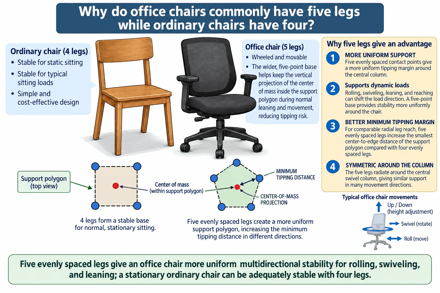
36. Why do office chairs commonly have five legs while ordinary chairs have four?Mechanical DesignEasy

Short Interview Answer (30-60 seconds)

Office chairs are mobile, swivel, and often allow leaning, so the load direction can change as a person rolls, reaches, or shifts position. Five evenly spaced legs form a more uniform support polygon around the central column. For the same approximate radial leg reach, a five-point layout has a larger minimum center-to-edge distance than a four-point layout, which improves the minimum tipping margin in different directions. A normal four-legged chair is mainly stationary, so four legs are usually adequate and simpler to manufacture.

Detailed Explanation

The main difference is the load case. An ordinary chair normally stays in one place, while an office chair can roll, swivel, change height, and support a person leaning or reaching in different directions. Because of that motion, the office-chair base should provide similar tipping resistance around the central column rather than being strong in only a few directions.

A chair remains statically stable while the vertical projection of the combined center of mass stays inside the support polygon formed by its ground-contact points. Tipping begins when that projection reaches a support edge and moves beyond it. A useful geometric measure is therefore the minimum distance from the center to any edge of the support polygon: a larger minimum distance gives more margin before tipping for a comparable center-of-mass position and load direction.

For a simplified comparison, assume the leg contact points are evenly spaced and have the same radial reach R from the center. For a regular n-sided support polygon, the center-to-edge distance is r = R cos(π/n). With four evenly spaced legs, r = R cos(45°) ≈ 0.707R. With five evenly spaced legs, r = R cos(36°) ≈ 0.809R. Under that equal-radius assumption, the five-point layout has a greater minimum center-to-edge distance and therefore a more uniform tipping margin around the chair. This does not mean that any five-legged chair automatically has a larger footprint or is always more stable than any four-legged chair; actual stability still depends on leg reach, seat height, center-of-mass location, caster position, user position, and applied loads.

The five legs also radiate naturally around the central swivel column, giving similar support in many movement directions. Casters provide mobility, but that mobility makes multidirectional stability especially important because rolling, swiveling, leaning, and reaching can shift the load direction.

A conventional four-legged chair has a different requirement. It is generally used for normal stationary sitting, so a four-contact-point support polygon can provide adequate stability. Four legs also give a simple structure with fewer parts and straightforward manufacturing and assembly. Adding another leg would increase material, part count, and assembly effort without necessarily providing enough benefit for that operating condition.

Useful Questions to Ask the Interviewer
  • Are we comparing chairs with approximately the same radial leg reach or overall footprint?
  • Does the office chair have casters, swivel, recline, or adjustable seat height?
  • What user load range, seat-height range, and floor conditions should the design cover?
  • Are there specific stability-test or footprint constraints that the design must meet?
Why do office chairs commonly have five legs while ordinary chairs have four? diagram
How to Explain It in an Interview

Start with the use case: an office chair experiences multidirectional loading because it rolls, swivels, and allows the user to lean or reach. Then explain the support polygon and state that the vertical projection of the combined center of mass must remain inside it for static stability. Next, compare equal-radius four- and five-point layouts and show that the five-point layout has a greater minimum center-to-edge distance, so it provides a better minimum tipping margin in different directions. Finally, mention the tradeoff: a stationary ordinary chair can be adequately stable with four legs, so the simpler four-leg structure avoids unnecessary material, parts, and assembly. For a real design, validate the final geometry using representative forward, rearward, and lateral tipping tests across the intended seat-height range and with the actual casters and floor conditions rather than relying on the simplified support-polygon model alone.

Practical Complexity & Trade-offs

The design tradeoff is stability versus simplicity. Five evenly spaced legs give a mobile office chair more uniform tipping resistance around its central column, especially when the user can roll, swivel, lean, or reach. The cost is an additional leg, caster, material, manufacturing step, and assembly interface. Four legs are usually enough for a stationary chair, so adding a fifth leg may provide little practical benefit there. Real stability also depends on base radius, seat height, center-of-mass location, caster geometry, floor conditions, structural stiffness, and the actual load cases, so leg count alone is not a complete measure of stability.

Why Interviewers Ask This

Interviewers are checking whether you can connect a familiar product feature to basic mechanical-design reasoning: load cases, support geometry, center-of-mass projection, tipping stability, operating conditions, and design tradeoffs. A strong answer should explain why the number and arrangement of contact points follow from how the chair is used rather than treating five legs as an arbitrary convention.

Interviewer may ask next
How would you validate that a five-leg office-chair base is actually stable enough?

I would define the expected user loads, seat-height range, caster configuration, floor condition, and likely leaning or reaching directions. Then I would evaluate the support polygon and check the center-of-mass projection under representative load cases. After that, I would prototype the chair and perform controlled forward, rearward, and lateral stability tests at the most critical configurations, such as maximum seat height and unfavorable load positions. I would also inspect the legs, central column, caster interfaces, and joints for deformation or damage. The simplified geometry helps choose a concept, but physical validation is needed before approving a real chair.

Could a four-leg office-chair base be as stable as a five-leg base?

Yes, if its geometry were changed enough. A four-leg base with greater radial reach could achieve the same or greater minimum tipping distance as a smaller five-leg base. The advantage of five evenly spaced legs is that, for comparable radial reach, they provide a greater minimum center-to-edge distance and more uniform multidirectional support. Therefore, five legs are a practical way to obtain good stability without making the base excessively wide, but the final decision should compare footprint, stability, cost, manufacturability, and intended use.

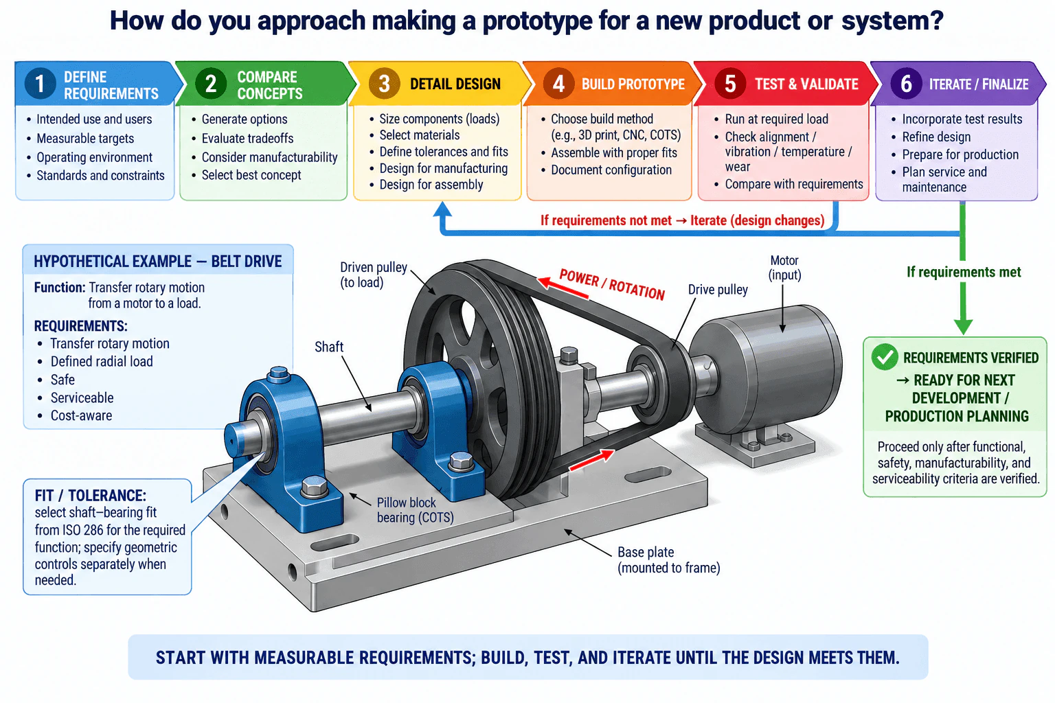
37. How do you approach making a prototype for a new product or system?Mechanical DesignEasy

Short Interview Answer (30-60 seconds)

I start by defining the intended use, interfaces, operating environment, measurable targets, load cases, and constraints. Then I generate and compare concepts based on performance, safety, manufacturability, cost, and serviceability. After selecting a concept, I size the important components, choose materials, define fits and tolerances, and plan manufacturing and assembly. I build the simplest prototype that can answer the main engineering questions, test it at the required operating conditions, compare the results with the original requirements, and iterate on the design until the required criteria are verified.

Detailed Explanation

A prototype should answer engineering questions, not simply look like the final product. My approach is to move from measurable requirements to a buildable design, test it against those requirements, and use the results to decide what needs to change.

Useful Questions to Ask the Interviewer
  • What is the main function the product or system must perform?
  • What measurable targets define success, such as load, speed, accuracy, life, size, temperature, noise, or cost?
  • What mechanical interfaces must the prototype connect to?
  • What operating environment and load cases should it represent?
  • Which requirements are safety-critical or technically uncertain?
  • Is the prototype intended to prove basic function, verify performance, evaluate manufacturing, or approximate the production design?
  • What manufacturing processes, standard components, budget, and schedule are available?
  • Which components must remain accessible for assembly, adjustment, inspection, or service?
How do you approach making a prototype for a new product or system? diagram
How to Explain It in an Interview

I would explain the process as six connected stages.

  1. Define requirements.

I begin with intended use and users, then translate those needs into measurable engineering requirements. I define the important interfaces, expected load cases, operating environment, packaging constraints, service needs, and relevant standards or safety constraints. I also identify unknowns because those usually determine what the prototype needs to prove.

For a hypothetical belt-drive prototype, for example, the function is to transfer rotary motion from a motor to a load. Before selecting hardware, I would define the required motion and loading, shaft and mounting interfaces, available space, operating environment, serviceability expectations, cost constraints, and measurable acceptance criteria. I would not invent a design load or performance target that has not been supplied or justified.

  1. Compare concepts.

I generate several feasible concepts and compare their tradeoffs. Typical criteria include performance, safety, manufacturability, assembly effort, cost, maintainability, and availability of standard parts.

For the belt-drive example, concept decisions could include the shaft arrangement, pulley locations, bearing support, belt-tensioning method, base structure, and access for service. The goal is to select the concept that best satisfies the requirements with acceptable technical risk, not simply the most complex option.

  1. Develop the detailed design.

After selecting the concept, I size the critical components using the expected loads, suitable material data, and appropriate failure criteria. I choose materials according to the properties that matter for the application, such as strength, stiffness, wear resistance, operating environment, manufacturability, and cost.

I then define the important interfaces. In the illustrated rotating assembly, those include the motor and drive pulley, belt, driven pulley, shaft, pillow-block bearings, fasteners, and base plate. Fits and tolerances should come from functional needs rather than being made unnecessarily tight. Where applicable, ISO 286 tolerance classes can support dimensional fit selection, while bearing-manufacturer guidance and separate geometric controls may also be needed for the actual shaft and bearing interface.

I also consider design for manufacturing and design for assembly. I check whether the parts can be made with the available processes, whether commercial off-the-shelf components can replace custom parts, whether tools can reach the fasteners, whether the assembly sequence is practical, and whether wear items can be serviced.

  1. Build the prototype.

I choose the prototype method according to what I need to learn. Depending on the required fidelity, I might use machining, additive manufacturing, fabricated parts, or commercial off-the-shelf components. The prototype does not automatically need production materials or production manufacturing methods if those details are not part of the question being tested.

In the hypothetical belt-drive assembly, the motor turns a small drive pulley. The belt transfers rotation to the larger driven pulley, which turns the supported shaft and connected load. Pillow-block bearings support the shaft, and the base plate locates and supports the assembly. That creates a clear physical power path from the motor to the load.

I document the prototype configuration so that every test result can be traced to the exact hardware that was evaluated.

  1. Test and validate.

I test the prototype against the original requirements rather than judging it subjectively. For the belt-drive example, that can include operation at the required load, checking alignment, observing vibration and temperature where relevant, inspecting for interference or wear, and comparing measured behavior with the defined acceptance criteria.

A functional test alone does not prove that the complete design is safe, reliable, manufacturable, or ready for production. Each important requirement needs appropriate evidence before I consider it verified.

  1. Iterate or finalize.

If the prototype does not meet a requirement, I trace the problem back to the relevant design decision and return to detailed design. For example, excessive vibration could lead me to investigate alignment, pulley balance, belt tension, shaft stiffness, bearing support, mounting stiffness, or resonance instead of changing parts randomly.

I update the design, rebuild only what is necessary, and repeat the affected validation tests. This creates the same feedback loop shown in the prototype process: failed criteria return to design changes, while verified criteria allow the project to move toward the next development or production-planning stage.

I would only move forward after the required functional, safety, manufacturability, and serviceability criteria have been verified to the level appropriate for that development stage. I would also document the design decisions, open risks, test evidence, and any remaining work.

The main principle is simple: start with measurable requirements, build a prototype that answers the important engineering questions, test it under meaningful conditions, and iterate until the design meets the defined requirements.

Practical Complexity & Trade-offs

The main tradeoff is prototype fidelity versus time, cost, and learning value. An early prototype can be inexpensive and simple if it only needs to prove a basic function, while a later prototype may need realistic materials, tolerances, interfaces, loads, and manufacturing processes. Tighter tolerances can improve control of an interface but increase manufacturing cost and assembly difficulty. Standard components can reduce cost and lead time but may limit packaging flexibility. A larger or stiffer shaft can reduce deflection but may increase mass, cost, and packaging needs. The best prototype is therefore not necessarily the one that looks most like the final product; it is the one that provides the evidence needed to make the next engineering decision.

Why Interviewers Ask This

Interviewers want to see whether you can turn an idea into a testable mechanical design in a disciplined way. They are evaluating whether you begin with measurable requirements, compare concepts, understand loads and interfaces, make reasonable material and tolerance decisions, consider manufacturability and assembly, validate the prototype under meaningful operating conditions, and use test results to drive design changes instead of treating the first build as the finished design.

Interviewer may ask next
What would you do if the prototype performs its basic function but shows excessive vibration during testing?

I would first confirm that the test setup and operating condition are correct, then investigate likely causes such as pulley misalignment, imbalance, incorrect belt tension, shaft deflection, bearing condition, loose fasteners, insufficient base stiffness, or resonance. I would measure the behavior where practical, compare it with the acceptance criterion, and make a justified design change rather than changing several variables at once. After the change, I would repeat the affected validation test and document whether the requirement is now satisfied.

How would your prototype approach change if the budget and schedule became much tighter?

I would reduce the prototype scope rather than remove critical validation. I would identify the highest-risk assumptions and build only enough hardware to test those first. I would favor standard components, simpler manufacturing methods, reusable fixtures, and modular parts where appropriate. Lower-risk cosmetic or production-detail features could be deferred. The tradeoff is lower prototype fidelity, so I would clearly document which requirements were actually verified and which still require validation before the design can progress.

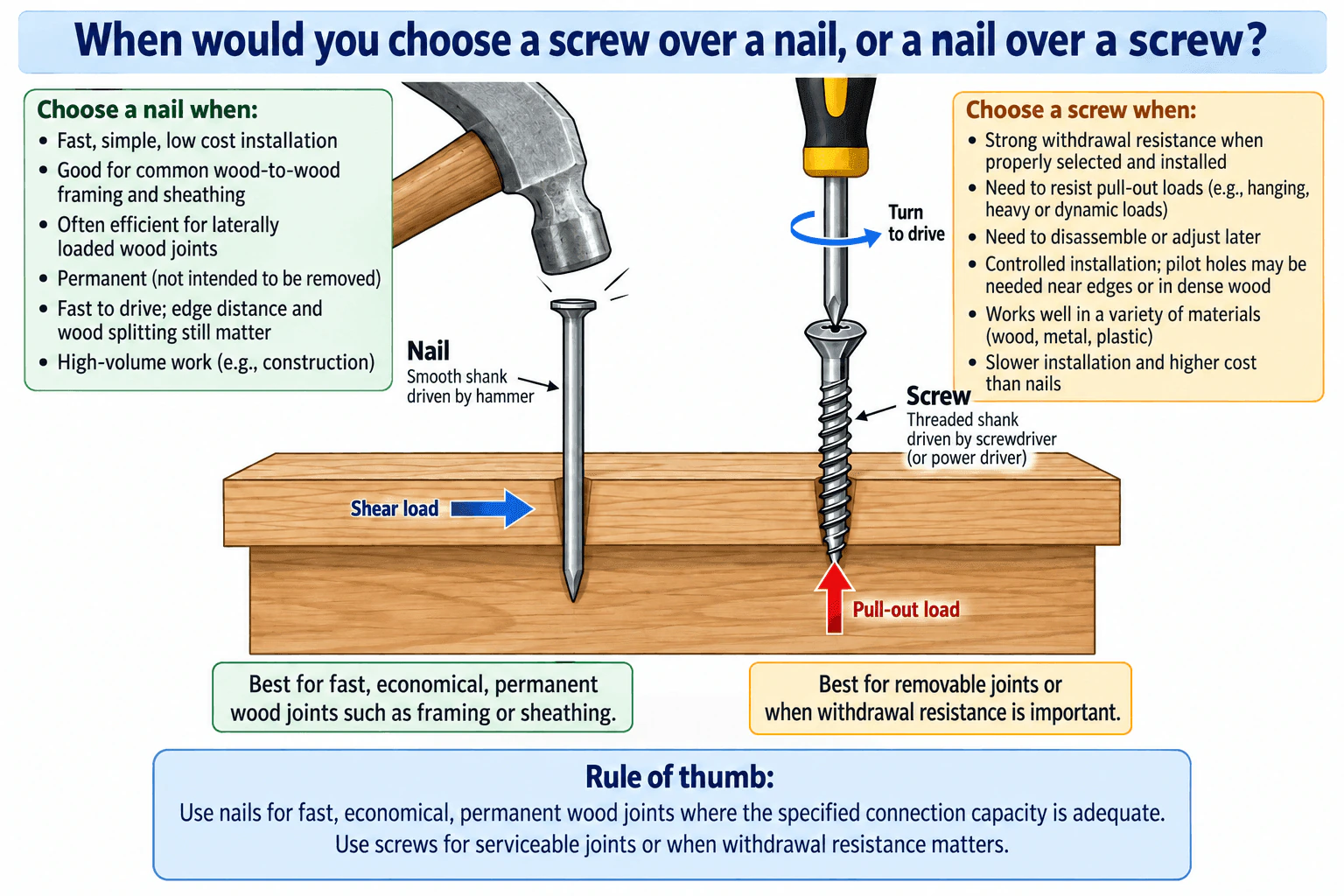
38. When would you choose a screw over a nail, or a nail over a screw?Mechanical DesignEasy

Short Interview Answer (30-60 seconds)

I would usually choose a nail for fast, low-cost, permanent wood joints such as framing or sheathing when the required connection capacity is adequate. I would choose a screw when withdrawal resistance, controlled installation, adjustment, or later disassembly matters more. Both nails and screws can carry lateral and withdrawal loads, so I would make the final choice from the actual load case, materials, fastener geometry, installation conditions, and serviceability needs.

Detailed Explanation

The basic decision is driven by the joint requirements, not by a rule that one fastener is always stronger. Nails are often a good choice for fast, economical, permanent wood-to-wood assembly. Screws are often preferred when withdrawal resistance, controlled installation, adjustment, or later disassembly is important.

Design Path

  1. Define the interface. Identify what materials are being joined and whether the connection is permanent or serviceable.
  2. Define the load case. Determine whether the joint is mainly laterally loaded, mainly loaded in withdrawal, or sees a combination of both.
  3. Compare installation needs. Nails are quick to drive and work well for high-volume wood construction. Screws generally take longer and cost more, but they provide controlled installation and can be removed later.
  4. Check material and geometry limits. For wood connections, edge distance, end distance, penetration, fastener diameter, wood density, and splitting risk all matter. Pilot holes may be appropriate near edges or in dense wood, depending on the screw and material.
  5. Check serviceability. If the joint will be adjusted, repaired, or disassembled, a screw is usually the more practical choice.

Design Checks

  • Nail choice: suitable when fast installation, low cost, a permanent joint, and adequate lateral or combined connection capacity are the main requirements.
  • Screw choice: suitable when withdrawal resistance is important, the joint may need to be removed or adjusted, or controlled installation is valuable.
  • Load capacity: do not assume every screw is stronger than every nail. Capacity depends on fastener type, diameter, length, penetration, material properties, joint geometry, and loading direction.
  • Splitting: nails and screws can both split wood if geometry or installation is poor. Edge distance and installation method must be considered.
  • Materials: use a fastener type intended for the materials being joined. Screws are available for wood, metal, and plastic applications, but the thread form and fastener specification must match the material.
  • Environment: if moisture or corrosion is possible, verify coating, fastener material, and compatibility with the connected materials.

Design Rationale For a common framing or sheathing joint, a nail is often attractive because it is fast, economical, and well suited to permanent high-volume wood assembly. For a joint that must resist withdrawal, be adjusted, or be taken apart later, a properly selected screw is often the better design choice. The diagram's shear-load and pull-out-load examples illustrate the decision drivers, but they should not be interpreted as saying nails only resist shear or screws only resist withdrawal; both fastener types can resist both load components when properly designed.

Assumptions and limits No fastener dimensions, wood species, load magnitudes, environment, or required design margin are given. Therefore, this is a concept-level selection method, not a final fastener size or certified structural design. A real design would require the applicable connection design data or standard for the specific fastener and materials.

Validation Before release, I would verify the representative connection against the required lateral and withdrawal loads, inspect for splitting or stripping during installation, and confirm assembly repeatability. If serviceability is important, I would also confirm that removal and reassembly do not damage the joint beyond the allowed condition.

Conclusion Use nails for fast, economical, permanent wood joints where the specified connection capacity is adequate. Use screws for serviceable joints or when withdrawal resistance and controlled installation are important. Make the final decision from the actual joint requirements rather than from a universal nail-versus-screw strength rule.

Useful Questions to Ask the Interviewer
  • Is the joint intended to be permanent, adjustable, or removable?
  • What materials are being joined?
  • What is the dominant load case: lateral, withdrawal, or combined loading?
  • Is this a high-volume assembly where installation speed and cost dominate?
  • Are there edge-distance, splitting, or pilot-hole constraints?
  • Will the joint require maintenance or repeated access?
  • What environmental or corrosion conditions must the fastener withstand?
When would you choose a screw over a nail, or a nail over a screw? diagram
How to Explain It in an Interview

I would say that I start with the joint requirements. If it is a fast, economical, permanent wood connection such as framing or sheathing, I would usually consider a nail. If withdrawal resistance, controlled installation, adjustment, or future disassembly matters more, I would usually consider a screw. I would then qualify that both nails and screws can resist lateral and withdrawal loads, so the final design must use the actual fastener geometry, materials, joint layout, environment, and required capacity. That shows the choice is based on engineering requirements rather than a blanket rule.

Practical Complexity & Trade-offs

The question is simple conceptually, but the real tradeoff is practical. Nails usually favor speed, low cost, and permanent high-volume wood assembly. Screws usually favor withdrawal resistance, controlled installation, and serviceability. The final engineering choice also depends on fastener size, penetration, material, edge distance, splitting risk, corrosion, and the actual lateral and withdrawal loads. No Big O or programming complexity applies.

Why Interviewers Ask This

Interviewers use this question to evaluate whether you can choose a fastener from the joint requirements instead of relying on a simplistic rule. They are looking for judgment about load direction, withdrawal versus lateral resistance, installation speed, cost, material compatibility, splitting risk, service access, and whether the joint must be permanent or removable.

Interviewer may ask next
What would you validate before finalizing the fastener selection?

I would confirm the actual lateral and withdrawal loads, the materials being joined, fastener diameter and length, penetration, joint geometry, edge and end distances, environmental exposure, and whether the joint must be removable. Then I would check the connection capacity using the appropriate design data for that fastener and validate a representative assembly for splitting, stripping, loosening, and installation repeatability.

How would your choice change if the joint must be disassembled for maintenance?

That requirement would generally favor a screw because serviceability becomes a primary design need. I would accept the slower installation and usually higher cost in exchange for easier removal and adjustment. I would still check whether repeated disassembly could damage the substrate; for frequent cycles, a more durable threaded interface such as an insert or nut-and-bolt arrangement may be more appropriate than repeatedly driving a screw directly into the same material.

39. How would you design a resistor mounting?Mechanical DesignMedium

Question Details

Identify the information needed before starting, suitable materials, and appropriate manufacturing processes.

Short Interview Answer (30-60 seconds)

I would first define the resistor type and electrical requirements, expected power dissipation, allowable temperature, ambient temperature and airflow, mounting space and orientation, vibration and shock loads, terminal and wire interfaces, electrical clearance or isolation requirements, service access, production volume, cost, and applicable product or agency requirements. For an aluminum-housed chassis-mount resistor, I would mount its integral flanges directly to a metal chassis or heatsink with specified fasteners and washers, using the manufacturer-recommended thermal compound or another qualified thermal interface at the resistor base. Aluminum is attractive where heat spreading and low mass matter, while steel can be useful where stiffness, durability, or cost dominate. I would purchase the resistor as a standard component, manufacture the chassis or bracket by sheet-metal forming or machining as appropriate, and validate temperature, fastener retention, electrical clearance or isolation, assembly access, and manufacturing consistency.

Detailed Explanation

The design should start with requirements and interfaces, not with bracket geometry. I would treat the resistor, its integral mounting flanges, thermal interface, chassis or heatsink, mounting fasteners, electrical terminals, and connected wires as one assembly. The main thermal path is from the resistor base through the thermal-interface material into the chassis or heatsink. Heat is also rejected from exposed resistor and chassis surfaces to the surrounding air. The mounting hardware must hold the component securely without interfering with the electrical terminals, wire routing, or service access.

Useful Questions to Ask the Interviewer
  • What type of resistor is being mounted, and is it designed for chassis or heatsink mounting?
  • What resistance, tolerance, voltage, and power-dissipation requirements apply?
  • What maximum resistor or base temperature is permitted by the selected component specification?
  • What are the minimum and maximum ambient temperatures, and is cooling by natural or forced airflow?
  • How much mounting space is available, and what orientations are allowed?
  • What vibration, shock, or other mechanical loads must the assembly withstand?
  • What terminal style, wire size, routing, bend space, and service clearances are required?
  • What electrical clearance or isolation requirements apply to the finished product?
  • Is the resistor expected to be field replaceable?
  • What production volume, cost target, available manufacturing processes, and applicable safety or agency requirements apply?

These questions separate supplied facts from assumptions. I would not select dimensions, tightening torque, a locking method, a thermal-interface thickness, or a safety margin until the actual resistor data, loads, environment, and manufacturing constraints are known.

How would you design a resistor mounting? diagram
How to Explain It in an Interview

First, I would select a resistor that is designed for chassis or heatsink mounting rather than create a custom resistor housing. A suitable concept is an aluminum-housed power resistor with integral mounting flanges. Those flanges provide defined mechanical attachment points while allowing the flat resistor base to transfer heat into the mounting surface.

For the thermal interface, I would follow the selected resistor manufacturer's mounting instructions. A manufacturer-recommended thermal compound is one common approach. A qualified interface pad can also be used when the component specification and product design call for it. I would not automatically add an electrically insulating ceramic layer because that may not be required and could increase thermal resistance. The intended thermal path is resistor base to thermal interface to chassis or heatsink, followed by heat rejection from the chassis and exposed resistor surfaces to the ambient air.

For the chassis or bracket, aluminum is attractive when thermal conductivity and low mass are important. Steel may be attractive when stiffness for a given geometry, durability, fabrication capability, or material cost is more important. The final material choice depends on thermal performance, mechanical loads, corrosion environment, geometry, manufacturing process, cost, and service requirements.

The resistor would be secured through its integral mounting flanges using specified fasteners and washers. Stainless-steel hardware can be a useful corrosion-resistant choice when compatible with the joint and environment, but the actual fastener material should be selected from the design requirements. Fastener size, thread engagement, tightening torque, and any locking feature must come from the actual joint design and component guidance. A plain washer should not be treated as a vibration-locking device. If vibration requires additional retention, I would use an appropriate locking method compatible with temperature, serviceability, material pairing, and the production process.

The electrical terminals and insulated wires must remain separate from the mounting hardware. I would check terminal access, wire bend space, strain relief if required, conductor temperature capability, and the required electrical clearance or isolation. I would also make sure technicians can reach the mounting hardware and terminals if the resistor is intended to be replaced during service.

For manufacturing, I would normally specify and purchase the aluminum-housed resistor as a standard component. The chassis or mounting bracket could be produced by sheet-metal stamping and bending when the geometry and production volume support it, or by machining where lower volume, geometry, or tolerance requirements justify it. Mounting holes can be punched, drilled, or machined depending on the selected process. During assembly, the specified thermal compound would be applied, or a qualified pad would be installed if the design requires one.

The assembly sequence should also be defined. A practical sequence is to prepare the mounting surface, apply or install the specified thermal-interface material, position the resistor on the chassis, fasten the integral mounting flanges using the specified hardware and tightening procedure, and then complete the electrical connections without placing unintended loads on the terminals.

I would review the major failure modes before release. These include excessive resistor temperature caused by inadequate heat rejection or poor thermal contact, fastener loosening or loss of clamp load under vibration, damage to mounting flanges, electrical clearance or isolation problems, damaged terminals or wires, corrosion, inaccessible service hardware, and inconsistent application of thermal-interface material or fastener torque.

Validation should represent the real operating envelope. I would measure resistor or base temperature at the worst-case expected power and ambient condition and compare it with the selected component's allowable limits. I would verify fastener retention under the required vibration or shock environment, inspect electrical clearance or isolation, confirm assembly and service access, and inspect manufacturing quality and repeatability. If a requirement is not met, I would revise the chassis geometry or material, thermal interface, mounting method, wire layout, airflow, or component selection and then repeat the affected validation.

The outcome is a manufacturable resistor-mounting concept with a defined thermal path, secure mechanical attachment, controlled electrical interfaces, suitable material and process choices, service access, and a validation plan. It should not be called a proven or safe design until those requirements have been verified with the actual component and operating conditions.

Practical Complexity & Trade-offs

The main tradeoffs are thermal performance, mechanical strength and stiffness, electrical isolation, vibration resistance, manufacturing cost, assembly effort, and serviceability. Aluminum can improve heat spreading and reduce mass, while steel may provide higher stiffness for the same geometry or fit an established low-cost fabrication process. Thermal compound can reduce contact resistance but adds a controlled application step; a qualified pad can simplify handling in some assemblies but may add thermal resistance. A locking feature can improve fastener retention in vibration but may increase cost or make service harder. Sheet-metal forming is efficient for suitable production volumes, while machining is more flexible for low-volume or complex parts. Validation effort increases as temperature range, vibration severity, electrical requirements, and manufacturing variability become more demanding.

Why Interviewers Ask This

Interviewers want to see whether you can turn an open-ended mounting problem into measurable requirements, define the thermal and mechanical load paths, select appropriate materials and manufacturing processes, manage electrical and service interfaces, recognize important failure modes, and create a practical validation plan instead of jumping directly to a bracket shape.

Interviewer may ask next
How would you validate that the resistor mounting has adequate thermal performance?

I would first define the actual worst-case resistor power dissipation, ambient temperature, airflow, mounting orientation, duty cycle if relevant, and the allowable temperature from the selected resistor documentation. I would build a representative assembly using the intended chassis material, geometry, fasteners, and thermal interface. I would then operate it under the defined worst-case condition and measure the resistor or base temperature and relevant chassis temperatures after the required thermal condition is reached. I would compare those measurements with the component limits while considering measurement uncertainty and production variation. If temperatures are too high, I would improve the thermal path by changing the effective heatsink area, chassis material or geometry, interface condition, airflow when permitted, or resistor selection, and then repeat the affected validation.

How would the design change if the assembly had to operate in a high-vibration environment?

I would keep the same basic chassis-mount concept but place more emphasis on fastener retention, clamp-load stability, wire support, terminal loading, and fatigue. I would define the required vibration and shock environment, verify that the selected resistor and terminals are suitable, choose a fastener and locking method appropriate to that environment, and make sure the joint does not overstress the resistor's integral mounting flanges. I would also support the wires so vibration is not transferred directly into the terminals. The completed assembly would then be subjected to the specified vibration or shock validation, followed by inspection of fastener retention, flange or chassis damage, terminal integrity, electrical continuity or isolation as applicable, and any degradation of the thermal interface.

40. How would you integrate a stylus into a device?Mechanical DesignMedium

Question Details

Explain how it would be stored and charged, and what it could be used for.

Short Interview Answer (30-60 seconds)

I would integrate a rechargeable active stylus into a dedicated bay in the device frame so it is protected, easy to access, and charged while stored. A spring-loaded latch would retain it, a magnet would help align it as it is docked, and spring-loaded pogo-pin contacts would connect it to the device charging circuit. The user would push the stylus into the bay to store and charge it and pull it out when needed. I would design it for handwriting, sketching and drawing, document annotation, and precise input such as selection, editing, or CAD work, then validate retention, insertion and removal, charging reliability, wear, drop performance, and tolerance variation.

Detailed Explanation

I would treat the stylus, device-frame storage bay, spring-loaded latch, alignment magnet, pogo-pin charging interface, and surrounding housing as one integrated mechanical system. The design objective is to keep the stylus secure, protected, easy to remove, and automatically charged whenever it is docked. I would not choose final dimensions or forces until the device packaging, manufacturing processes, expected environment, user-force targets, and charging requirements are known.

Useful Questions to Ask the Interviewer
  • What type of device is this, and how much internal packaging space is available for the stylus bay?
  • Does the stylus need to sit completely flush with the device exterior when stored?
  • What insertion, extraction, and retention-force targets should the design meet?
  • What drop, vibration, contamination, and environmental conditions should the stored stylus survive?
  • What charging power and battery-life targets apply to the active stylus?
  • Is one-handed removal required?
  • Which primary uses matter most: handwriting, sketching and drawing, document annotation, precise selection and editing, or CAD-style input?
  • What manufacturing process, cost target, service strategy, and assembly constraints apply?
How would you integrate a stylus into a device? diagram
How to Explain It in an Interview

I would start by defining the interfaces. Mechanically, the stylus must slide into a controlled storage path, be retained against accidental release, and remain easy to remove. Electrically, the stylus must repeatedly land on the charging contacts with enough alignment accuracy and contact force to charge reliably. From the user's perspective, the storage and removal action should be simple and deliberate.

For storage, I would place a dedicated stylus bay inside the device frame, matching the concept shown in the approved design. The bay guides the stylus along a single insertion path and protects most of the stylus body while stored. I would design the guide clearance from the actual stylus and housing tolerances so the stylus does not rattle excessively but also does not bind when parts are at tolerance limits. The exact clearance would be derived from the selected manufacturing processes rather than guessed.

For retention, I would use the spring-loaded latch as the primary mechanical feature that holds the stylus in the bay. The magnet would assist alignment near the fully docked position so the stylus seats consistently, but I would not rely on the magnet alone for positive retention. This separates the functions clearly: the latch resists accidental removal, while the magnet helps place the stylus correctly for docking and charging.

For charging, I would use spring-loaded pogo pins in the device and matching conductive contacts on the stylus. As the user pushes the stylus fully into the bay, the alignment feature positions the charging end so the pogo pins compress against the stylus contacts. The pogo-pin travel accommodates small positional and tolerance variation while maintaining electrical contact. The device charging electronics can then recharge the stylus battery while it remains stored. I would arrange the contacts so normal insertion does not impose excessive lateral loads on the pins.

The user interaction would follow the diagram directly: push the stylus into the bay to dock, align, retain, and charge it; pull it from the bay when needed. The grip and latch geometry should make removal intentional without requiring excessive force or creating pinch points or sharp edges.

The stylus could then be used for handwriting notes, sketching and drawing, annotating documents, and precise input such as selecting, editing, or CAD-related interaction. Those uses justify keeping the stylus available and charged instead of treating it as a separate accessory.

The main design tradeoffs are packaging volume versus device thickness, stronger retention versus comfortable removal, tighter guidance versus tolerance sensitivity and friction, magnetic alignment strength versus interaction with nearby ferromagnetic components, and pogo-pin contact preload versus wear. An internal bay also gives a clean, flush exterior and good protection, but it consumes internal volume and adds latch, charging-contact, and assembly complexity.

Important failure modes include excessive rattle from too much clearance, jamming from an overly tight tolerance stack, accidental stylus release from insufficient latch retention, intermittent charging from contact contamination or misalignment, pogo-pin wear or damage, latch wear, magnet misalignment, and housing damage if impact loads are transferred through the stored stylus. I would review these in a design FMEA and use the highest-risk items to drive prototype testing.

For design for assembly and serviceability, I would make the latch and charging-contact region accessible during assembly without requiring an unnecessarily complicated sequence. If the product architecture allows it, a damaged latch or charging-contact module should be replaceable without replacing unrelated device components.

For validation, I would build prototypes and measure insertion force, extraction force, retained-stylus movement, and electrical contact continuity. I would cycle the stylus through repeated insertions and removals to assess latch, guide, coating, and pogo-pin wear. I would also perform representative drop and vibration tests with the stylus stored, charging-performance tests while docked, contamination testing appropriate to the product environment, and tolerance-limit builds to check for binding or poor contact. User testing would verify one-handed access, grip, and removal comfort if those are requirements.

My final concept is therefore a rechargeable active stylus stored in a protected bay in the device frame, held by a spring-loaded latch, aligned by a magnet, and automatically connected to pogo-pin charging contacts when pushed fully into the dock. It remains ready for handwriting, drawing, document annotation, and precise selection or editing while balancing security, charging reliability, manufacturability, durability, and serviceability.

Practical Complexity & Trade-offs

The hard part is balancing several physical requirements at once. The stylus bay must be compact but cannot be so tight that manufacturing variation causes binding. The spring-loaded latch must hold the stylus securely but still allow comfortable removal. The magnet should help alignment without being the only retention method. The pogo pins need enough travel and contact force for dependable charging but should not be side-loaded or worn excessively. An internal bay protects the stylus and keeps the exterior clean, but it consumes device volume and adds parts, assembly steps, and service considerations. I would resolve those tradeoffs with tolerance analysis, prototypes, repeated docking tests, charging tests, drop and vibration tests, and user-access testing.

Why Interviewers Ask This

Interviewers want to see whether I can turn a user-facing feature into a practical mechanical design by defining the storage, retention, alignment, charging, packaging, usability, tolerance, manufacturing, failure-mode, and validation requirements as one integrated system.

Interviewer may ask next
How would you validate that the stylus remains secure and charges reliably over the product life?

I would test the retention and charging interfaces together. I would measure insertion and extraction force across nominal and tolerance-limit builds, cycle the stylus through repeated docking and removal, monitor pogo-pin continuity and charging performance, and inspect the latch, guides, contacts, and stylus surfaces for wear. I would also perform representative drop and vibration tests with the stylus stored to confirm that the latch prevents accidental release and that impacts do not damage the bay or charging interface. If charging becomes intermittent, I would investigate alignment, pogo-pin travel, contact preload, contamination, wear, and the tolerance stack before changing the overall concept.

What would you change if the device became too thin to fit the internal stylus bay?

I would reconsider the storage architecture instead of forcing an inadequate cavity into the frame. An external docking location could free internal volume, but it would provide less physical protection and would require a different retention and charging arrangement. I would compare the internal and external concepts using device thickness, stylus protection, retention reliability, charging reliability, user access, manufacturability, cost, and serviceability. I would keep the internal bay only if the packaging study showed that it could fit without weakening the housing or interfering with other internal components.

More questions load as you scroll

Disclaimer: This interview guide is for educational and informational purposes only. It is designed to help readers prepare, but it does not guarantee any interview result, hiring decision, offer, or outcome. Interview questions, hiring criteria, and preferred answers can vary by employer, interviewer, industry, location, and time. All answers, examples, and explanations in this guide are suggested examples for interview preparation, not definitive answers or instructions for professional practice. They are based on research and judgment, are provided without warranties of any kind, and should be adapted to the question, role, and applicable laws and professional requirements. Diagrams are simplified illustrations intended to highlight the main concepts and their relationships; actual situations, systems, and practices may be more complex. Alternative approaches may be equally valid or better suited to a particular question, context, or interviewer. To the fullest extent permitted by applicable law, the contributors and publisher are not liable for decisions made, actions taken, or losses incurred based on this guide.

State Laws and Professional Responsibilities: Laws and requirements governing an occupation vary by state and jurisdiction. You are responsible for checking the current laws, licensing requirements, and scope-of-practice rules that apply to your location and role, and for ensuring that your answers and actions comply with them. Adapt examples in this guide to those requirements. This guide is not legal advice.

Content Accuracy and Verification: To the fullest extent permitted by applicable law, we do not represent or warrant that interview guides, questions, answers, examples, or diagrams are accurate, complete, current, error-free, or suitable for any particular purpose. You are responsible for independently reviewing and verifying the information before relying on it.