197 Mechanical Engineer Interview Questions & Answers

83 top • 12 Boeing • 9 Bosch • 12 Caterpillar • 9 Ford • 12 GE Aerospace • 12 Honeywell • 11 John Deere • 10 Lockheed Martin • 10 Rolls-Royce • 4 Siemens Energy • 10 Tesla • 3 Trane Technologies

Mechanical Engineer icon

Questions with Detailed ExplanationsWith Detailed Explanations

(Last Updated: September 13, 2026)

21. Describe your work on a project operating at cryogenic temperatures.Thermodynamics And Heat TransferHard

Question Details

Focus on a project involving very low operating temperatures.

Short Interview Answer (30-60 seconds)

On a cryogenic project, I would describe my contribution around controlling heat leak, managing cooldown, and accounting for material behavior at very low temperature. I would first define the cold boundary and operating range, then estimate conduction through supports, piping, wiring, and other penetrations, radiation from warmer surroundings, and convection or phase-change effects where applicable. I would use temperature-dependent properties rather than room-temperature constants, check differential thermal contraction at interfaces, and treat cooldown separately from steady-state operation. Finally, I would validate the thermal model using measured temperatures, cooldown behavior, pressure or flow data where relevant, and the observed refrigeration or cryogenic heat load.

Detailed Explanation

Because no specific project measurements or hardware details are supplied, I would not invent temperatures, dimensions, materials, loads, or test results. I would describe the engineering work in terms of the methods and decisions I would be responsible for on a cryogenic project.

The first step is to define the system boundary and operating conditions. I would identify the cold hardware, cryogenic fluid if present, surrounding environment, normal operating temperature, cooldown range, pressure condition, and required operating mode. I would define heat entering the cold region as positive.

I would then separate transient cooldown from steady-state operation because they answer different engineering questions. During cooldown, stored thermal energy and temperature gradients matter. At steady state, the key question is whether the refrigeration system or cryogenic fluid can continuously remove all incoming heat.

For steady operation, a simplified first-law balance for the cold region is:

Q̇_in − Q̇_removed = 0

where Q̇_in is the total heat entering the cold region and Q̇_removed is the heat continuously removed by the refrigeration system or cryogenic fluid.

I would break the incoming heat into identifiable physical paths:

Q̇_in = Q̇_conduction + Q̇_convection + Q̇_radiation + Q̇_penetrations + Q̇_other

Each term must be justified by the actual hardware and operating environment rather than automatically included or excluded.

For conduction through a structural support, pipe wall, electrical lead, or similar path, I would use temperature-dependent thermal conductivity when the temperature range is large. For a one-dimensional path with approximately constant cross-sectional area:

Q̇_cond = (A/L) ∫ from T_cold to T_hot k(T) dT

where A is the conduction area, L is the heat-flow length, k(T) is thermal conductivity as a function of temperature, T_cold is the cold-end absolute temperature, and T_hot is the warm-end absolute temperature. This avoids the common mistake of using a room-temperature conductivity value across the full cryogenic temperature range.

Radiation from warm surroundings can also be important. A simplified effective radiation relation is:

Q̇_rad = ε_eff σ A(T_hot^4 − T_cold^4)

where ε_eff is an effective emissivity representing the surface arrangement, σ is the Stefan-Boltzmann constant, A is radiating area, and both temperatures are in kelvin. Radiation shields, low-emissivity surfaces, or multilayer insulation can reduce this heat transfer, but their real performance depends on geometry, vacuum quality, surface condition, installation quality, and penetrations.

Convection depends on the environment. If the hardware operates in sufficiently high vacuum, ordinary gas convection can be greatly reduced, but I would not automatically assume it is zero without checking the pressure regime. If a gas or liquid directly contacts a surface, I would choose an appropriate convection, boiling, condensation, or two-phase model based on the fluid state, pressure, geometry, flow regime, and applicable correlation limits.

The cooldown phase requires a transient energy balance. A simplified lumped model is:

m c_p(T) dT/dt = Q̇_in − Q̇_cooling

where m is component mass, c_p(T) is temperature-dependent specific heat, T is component temperature, Q̇_in is heat entering the component, and Q̇_cooling is heat removed from it. For a large temperature change, I would normally integrate temperature-dependent heat capacity rather than assume one constant value. I would also check whether the lumped-temperature assumption is physically reasonable. If large internal gradients are expected, I would use a distributed transient thermal model instead.

Cryogenic operation also creates mechanical concerns because different materials contract by different amounts. I would estimate free thermal strain using:

ε_th = ∫ from T_reference to T_operating α(T) dT

where α(T) is the temperature-dependent coefficient of thermal expansion. If contraction is constrained, I would perform a structural assessment of the resulting stresses rather than treating the free-strain calculation as a complete stress result.

I would pay particular attention to supports, bolted joints, seals, welded or brazed interfaces, piping connections, sensor mounts, electrical feedthroughs, and other locations where thermal contraction or heat leakage can become important. Material selection would consider low-temperature thermal conductivity, strength, toughness, dimensional behavior, joining compatibility, working-fluid compatibility, and any applicable safety or certification requirements.

Instrumentation also matters because sensors and their wiring can change the system they are measuring. Wiring, tubes, feedthroughs, and supports can form unintended conductive heat paths. I would include those paths in the thermal model and place sensors where they can distinguish expected temperature gradients from localized heat leaks or poor thermal contact.

Validation would compare model predictions with measured behavior. During cooldown, I would compare temperature histories and gradients at selected locations. At steady state, I would compare measured temperatures and the observed or independently inferred refrigeration load with the calculated total heat leak. If mass flow and fluid-state measurements are available, an enthalpy balance may provide an additional first-law check.

If the model and measurements disagree, I would first examine sensor calibration and placement, boundary conditions, contact resistance, insulation condition, vacuum pressure, unexpected conductive paths, actual material properties, flow conditions, and operating changes. I would not simply tune uncertain model inputs until the results match.

The final engineering conclusion would be limited to the tested and analyzed operating range. A simplified calculation or simulation alone would not be enough to claim that real cryogenic equipment is safe or qualified for service.

Useful Questions to Ask the Interviewer
  • What are the normal operating temperature and the full startup or cooldown temperature range?
  • Is the cold region under vacuum, exposed to gas, or in direct contact with a cryogenic liquid?
  • What steady-state heat load is allowable, and what refrigeration capacity is available?
  • What cooldown time is required, and are there limits on thermal gradients or cooldown rate?
  • Which materials and interfaces experience the largest differential contraction?
  • Are boiling, condensation, flashing, or other phase-change effects expected?
  • What temperature, pressure, mass-flow, or refrigeration-load measurements are available for validation?
How to Explain It in an Interview

I would organize the explanation into four parts. First, I would define the operating temperature range, physical boundary, and whether I was analyzing cooldown, steady operation, or both. Second, I would explain the dominant heat-transfer paths and how I evaluated conduction, radiation, convection, phase change, and penetrations using properties appropriate to the actual temperature range. Third, I would explain cryogenic mechanical issues, especially differential thermal contraction and interface design. Fourth, I would describe how I validated the analysis using temperature histories, steady-state measurements, pressure or flow data where applicable, and an independent energy-balance check.

The strongest interview answer would connect each modeling decision to a physical reason. The main lesson is that cryogenic design is not simply ordinary heat transfer at a lower temperature. It requires temperature-dependent properties, careful control of small heat leaks, accommodation of contraction, separation of transient and steady behavior, and experimental validation before drawing conclusions about real hardware.

Technical Approach
  1. Define the cryogenic control volume, temperature range, pressure environment, working fluid if applicable, and heat-flow sign convention.
  2. Separate transient cooldown requirements from steady-state operating requirements.
  3. Identify every credible heat-transfer path, including structural conduction, piping, wiring, instrumentation, radiation, residual-gas or fluid convection, and justified process loads.
  4. Obtain material and fluid properties over the actual temperature range rather than relying on room-temperature constants.
  5. Calculate conductive heat leaks, integrating k(T) when conductivity varies significantly with temperature.
  6. Evaluate radiation using absolute temperature and the actual surface, shielding, and insulation arrangement.
  7. Include convection, boiling, condensation, or other phase-change effects only when supported by the actual pressure, fluid state, geometry, and flow regime.
  8. Sum the steady-state heat loads and compare them with available heat-removal capacity using a first-law energy balance.
  9. Model cooldown using transient energy storage and determine whether a lumped model is acceptable or a distributed model is required.
  10. Calculate differential thermal contraction using temperature-dependent expansion data and identify constrained interfaces that require stress analysis.
  11. Review supports, joints, seals, piping, wiring, feedthroughs, and instrumentation for both heat leakage and mechanical compatibility.
  12. Define measurements needed to validate temperature distribution, cooldown rate, pressure, flow, and heat load.
  13. Compare predictions with test data and investigate discrepancies through instrumentation, boundary conditions, insulation, vacuum condition, thermal contacts, material properties, and unmodeled thermal bridges.
  14. Limit the final engineering conclusion to operating conditions supported by the analysis and validation evidence.
Practical Insights

Cryogenic design involves several competing requirements. Stronger or more numerous supports can improve mechanical stiffness but can also conduct more heat into the cold region. Lower-conductivity supports may reduce heat leak but still have to meet strength, stiffness, vibration, and manufacturing requirements. More insulation or radiation shielding can reduce heat load but may increase packaging complexity, assembly difficulty, inspection effort, and sometimes cooldown time. A faster cooldown can reduce operating preparation time but may produce larger temperature gradients and differential contraction. Simple hand calculations and thermal-resistance models are useful for identifying dominant heat paths early, while more detailed transient or finite-element models become valuable when geometry, contact resistance, temperature-dependent properties, or internal gradients strongly affect the result. Test uncertainty also matters because a relatively small unmodeled heat leak may be important in a cryogenic system.

Why Interviewers Ask This

Interviewers want to evaluate whether I understand how thermal and mechanical behavior changes at cryogenic temperatures and whether I can translate those effects into sound engineering decisions. They are looking for judgment around defining thermal boundaries, estimating heat leaks, using temperature-dependent properties, accommodating thermal contraction, separating transient cooldown from steady-state operation, identifying failure modes, and validating analytical predictions against physical measurements.

Common interview mistakes

Common mistakes include using room-temperature material properties across the full cryogenic range; treating transient cooldown and steady-state operation as the same problem; using degrees Celsius instead of absolute temperature in radiation calculations; overlooking heat conducted through wiring, piping, fasteners, supports, and instrumentation; assuming vacuum eliminates every heat-transfer mechanism; ignoring differential thermal contraction; applying a convection or boiling correlation outside its valid regime; overlooking phase-change effects; treating a simplified thermal model as proof that the complete hardware is safe; failing to define the control-volume boundary and sign convention; and claiming specific performance without validated measurements or supplied project data.

Interview tip

Keep the answer organized around four ideas: operating conditions, heat-load model, cryogenic-specific mechanical risks, and validation. Emphasize what changes at very low temperature rather than giving a generic heat-transfer explanation. Mention temperature-dependent properties, parasitic conduction, radiation, appropriate convection or phase-change effects, differential contraction, transient cooldown, and experimental verification. Use project-specific dimensions, temperatures, materials, heat loads, and test results only when they come from your actual experience and you can explain how they were measured or calculated.
Interviewer may ask next
How would you validate that your predicted cryogenic heat load was correct?

I would validate both the overall energy balance and the temperature distribution. I would first verify sensor calibration, placement, and data acquisition because an instrumentation error can look like a modeling error. During cooldown, I would compare measured and predicted temperature histories and gradients at several locations. At steady state, I would compare the observed or independently inferred refrigeration load with the sum of the modeled heat inputs. If a flowing cryogenic fluid is present and reliable mass-flow and thermodynamic-state measurements are available, I could also perform an enthalpy balance using Q̇ = ṁ(h_out − h_in), with the sign convention defined consistently. If prediction and measurement disagree, I would investigate vacuum quality, insulation installation, thermal contacts, supports, wiring, piping, boundary temperatures, property data, flow conditions, and sensor behavior before changing model parameters. I would consider the model validated only over the conditions actually supported by the measurements.

What would change if the required cooldown time became much shorter?

A shorter cooldown requirement would make transient behavior more important. I would first determine whether the cooling system can remove the required stored thermal energy quickly enough. Because specific heat changes with temperature, I would calculate the energy that must be removed using temperature-dependent heat capacity rather than one room-temperature value. I would then check whether the higher cooling rate creates excessive internal temperature gradients, differential contraction, distortion, or interface stress. The cryogenic fluid or refrigeration system may also impose limits related to flow, pressure, phase change, or available cooling capacity. Depending on those results, possible design changes could include increasing available cooling capacity, improving selected thermal interfaces, reducing unnecessary thermal mass, changing the cooldown sequence, or accepting a longer cooldown. The choice would balance cooldown time against thermal stress, refrigeration capacity, mechanical reliability, system complexity, and validation evidence.

22. Which of air, mercury, water, and glass are fluids at room temperature and atmospheric pressure?Fluid Mechanics And Fluid SystemsEasy

Short Interview Answer (30-60 seconds)

At room temperature and atmospheric pressure, air, mercury, and water are fluids. Air is a gas, while mercury and water are liquids. All three continuously deform when subjected to sustained shear stress. Glass is an amorphous solid at room temperature, so it is not considered a fluid under these conditions.

Detailed Explanation

A fluid is a substance that continuously deforms when subjected to any sustained shear stress. This definition includes both liquids and gases.

At room temperature and atmospheric pressure:

  • Air is a fluid. It is a gas. It has no fixed shape and continuously deforms under shear stress.
  • Mercury is a fluid. It is a liquid metal under these conditions and flows when shear stress is applied.
  • Water is a fluid. It is a liquid and continuously deforms under applied shear stress.
  • Glass is not a fluid under these conditions. Ordinary glass is an amorphous solid at room temperature. It can sustain shear stress with a finite deformation instead of continuously flowing on normal engineering time scales.

Therefore, the correct classification is air, mercury, and water are fluids; glass is not.

The assumptions are the conditions stated in the question: ordinary room temperature, atmospheric pressure, and normal engineering observation time scales. No pressure-flow calculation, Reynolds-number check, or compressibility model is needed because this is a material-state and constitutive-behavior classification question rather than a flow-analysis problem.

A useful validation check is to apply the defining shear-stress test. Air, water, and mercury continue deforming as long as shear stress is maintained, whereas room-temperature glass behaves as a solid. The classification could change if the operating temperature changed enough to alter the material state or rheological behavior.

Useful Questions to Ask the Interviewer
  • Should I use ordinary room temperature and atmospheric pressure exactly as stated?
  • Should I classify the substances on normal engineering time scales rather than extremely long geological time scales?
  • Do you want the answer based on the fluid-mechanics definition of continuous deformation under sustained shear stress?

For the stated conditions, these clarifications do not change the result.

How to Explain It in an Interview

Start with the definition: a fluid continuously deforms when subjected to sustained shear stress. Then classify each material at the stated conditions. Air is a gas, so it is a fluid. Water and mercury are liquids, so they are also fluids. Glass behaves as an amorphous solid at room temperature and therefore is not classified as a fluid. The key point is that the word fluid includes both liquids and gases, not just liquids.

Technical Approach
  1. Use the engineering definition of a fluid: a substance that continuously deforms under sustained shear stress.
  2. Apply the specified conditions of room temperature and atmospheric pressure.
  3. Classify air as a gas and therefore a fluid.
  4. Classify mercury as a liquid and therefore a fluid.
  5. Classify water as a liquid and therefore a fluid.
  6. Classify ordinary glass as an amorphous solid at room temperature and therefore not a fluid on normal engineering time scales.
  7. Conclude that air, mercury, and water are fluids, while glass is not.
Practical Insights

No numerical calculation is required. The important physical consideration is that whether a material behaves as a fluid or solid can depend on temperature, pressure, and observation time scale. At room temperature, atmospheric pressure, and normal engineering time scales, air, mercury, and water behave as fluids, while glass behaves as a solid.

Why Interviewers Ask This

This question checks whether the candidate understands the fundamental definition of a fluid: a substance that continuously deforms when subjected to any sustained shear stress. It also tests whether the candidate recognizes that both liquids and gases are fluids, while ordinary solids are not classified as fluids under normal engineering conditions.

Common interview mistakes

A common mistake is saying that only water and mercury are fluids because they are liquids. Air is also a fluid because gases continuously deform under sustained shear stress. Another mistake is calling room-temperature glass a slowly flowing liquid. For normal engineering conditions and observation time scales, glass is an amorphous solid and is treated as a solid.

Interview tip

Give the classification immediately and then justify it using the definition of a fluid. A concise explanation is: 'Air, mercury, and water are fluids; glass is not at room temperature. Fluids include both gases and liquids because they continuously deform under sustained shear stress.'

Interviewer may ask next
What physical behavior distinguishes a fluid from a solid?

A fluid continuously deforms as long as a shear stress is applied. A solid can sustain a static shear stress with a finite deformation. This is why both liquids and gases are classified as fluids.

Could glass behave like a fluid if the temperature were increased?

Yes. As glass is heated through its glass-transition and softening range, its viscosity decreases substantially and it can exhibit increasingly viscous flow. Therefore, its mechanical behavior depends on temperature and time scale. At ordinary room temperature and atmospheric pressure, however, glass is treated as a solid.

23. Why are gases more easily compressed than liquids or solids?Fluid Mechanics And Fluid SystemsEasy

Short Interview Answer (30-60 seconds)

Gases are more easily compressed because their molecules are much farther apart than the molecules in liquids or solids. When pressure is applied, much of the space between gas molecules can be reduced, so the gas volume decreases significantly. In liquids and solids, the particles are already packed closely together, leaving much less space to remove. That is why liquids are often treated as nearly incompressible in ordinary fluid-system calculations, while gases frequently require compressible-flow analysis.

Detailed Explanation

Gases are easier to compress mainly because their molecules are widely separated. A gas contains molecules moving freely with relatively large distances between them. When external pressure increases, the average distance between the molecules can decrease substantially, producing a significant reduction in gas volume.

Liquids behave differently. Their molecules are already close together, although they can still move past one another. Because there is relatively little intermolecular space available to reduce, a large pressure increase normally produces only a small decrease in liquid volume.

Solids also have closely packed atoms or molecules, and their particles are constrained around relatively fixed positions. Further compression requires reducing interatomic or intermolecular spacing against strong bonding forces, so solids generally resist bulk compression strongly.

A useful engineering property for describing this behavior is the bulk modulus, K. For a small pressure-induced volume change, it can be written as K = -V(ΔP/ΔV), where V is the original volume, ΔP is the pressure change, and ΔV is the corresponding volume change. The negative sign accounts for the fact that volume decreases as pressure increases. A higher bulk modulus means greater resistance to compression. Liquids and solids generally have much higher bulk moduli than gases under ordinary conditions.

In fluid-system analysis, this distinction affects the assumptions used in calculations. Liquid flow is often modeled as incompressible when density changes are negligible for the required accuracy. Gas density can change significantly with pressure and temperature, so compressible-flow relationships may be necessary, particularly when pressure changes are large. The incompressible assumption is therefore an engineering approximation, not a statement that a liquid can never change volume.

Useful Questions to Ask the Interviewer
  • Are we discussing ordinary engineering pressures and temperatures, or very high pressures where liquid compressibility may become important?
  • Should I explain this only from a molecular viewpoint, or also relate it to bulk modulus and fluid-system modeling?
  • Are we assuming the gas remains in a single phase during compression?
How to Explain It in an Interview

Start with the simplest physical idea: gas molecules are far apart, so pressure can reduce the space between them. Contrast that with liquids and solids, where the particles are already closely packed. Then connect the explanation to engineering practice: liquids are commonly approximated as incompressible when density changes are small, while gases often require compressible-flow analysis because pressure and temperature changes can produce meaningful density and volume changes. A useful technical extension is to mention that materials with a high bulk modulus resist compression more strongly.

Technical Approach
  1. Identify the state of matter: gas, liquid, or solid.
  2. Compare the typical spacing between its particles.
  3. Determine what must change when external pressure increases.
  4. For a gas, recognize that much of the volume reduction can come from decreasing the relatively large spacing between molecules.
  5. For liquids and solids, recognize that the particles are already closely packed, so additional compression requires much stronger intermolecular or interatomic resistance to be overcome.
  6. Relate the behavior to bulk modulus: a higher bulk modulus means greater resistance to volume change.
  7. For a fluid-system calculation, determine whether density changes are small enough to justify an incompressible approximation or significant enough to require compressible-flow treatment.
Practical Insights

The main engineering tradeoff is modeling simplicity versus accuracy. Treating a liquid as incompressible simplifies continuity, pressure-loss, and hydraulic calculations and is usually reasonable when its density change is negligible. For gases, pressure and temperature changes can produce significant density changes, so an incompressible assumption can give inaccurate estimates of flow rate, velocity, pressure drop, and equipment performance. At sufficiently high pressures or during rapid pressure transients, liquid compressibility may also need to be considered.

Why Interviewers Ask This

Interviewers ask this to check whether the candidate understands how molecular spacing and intermolecular behavior affect compressibility. The key judgment is recognizing that gases contain much more space between molecules, so their volume can decrease substantially when pressure increases, while liquids and solids already have closely packed particles and resist further volume reduction.

Common interview mistakes

A common mistake is saying that gases are easier to compress because their molecules are smaller. Molecular size is not the main reason; the important difference is the much larger spacing between gas molecules. Another mistake is saying that liquids are perfectly incompressible. Real liquids do compress slightly, although the change is often small enough to neglect in ordinary engineering calculations. It is also a mistake to assume gas density remains constant when pressure changes are large enough for compressibility to matter.

Interview tip

Give the molecular-spacing explanation first because it directly answers the question. Then add one engineering connection: liquids are often approximated as incompressible, while gases more often require density changes to be considered. Mention bulk modulus only as a supporting technical concept rather than making the answer unnecessarily complicated.

Interviewer may ask next
Are liquids truly incompressible?

No. Real liquids are compressible, but their volume usually changes only slightly under ordinary pressure changes because their molecules are already closely packed. Engineers therefore often use an incompressible-flow approximation when the resulting density change is negligible for the required accuracy. At very high pressures or during rapid pressure transients, liquid compressibility can become important.

How does gas compressibility affect a pneumatic system compared with a hydraulic system?

A pneumatic system uses a compressible gas, so pressure changes can cause noticeable changes in gas volume and density. This gives the system more elastic or spring-like behavior and can affect response and positioning. A hydraulic system normally uses a much less compressible liquid, so pressure changes produce much smaller volume changes and generally provide stiffer force transmission. Real hydraulic systems still have some compliance because of liquid compressibility, component elasticity, flexible hoses, and any trapped gas.

24. Why does a fluid at rest exert force perpendicular to a surface?Fluid Mechanics And Fluid SystemsEasy

Short Interview Answer (30-60 seconds)

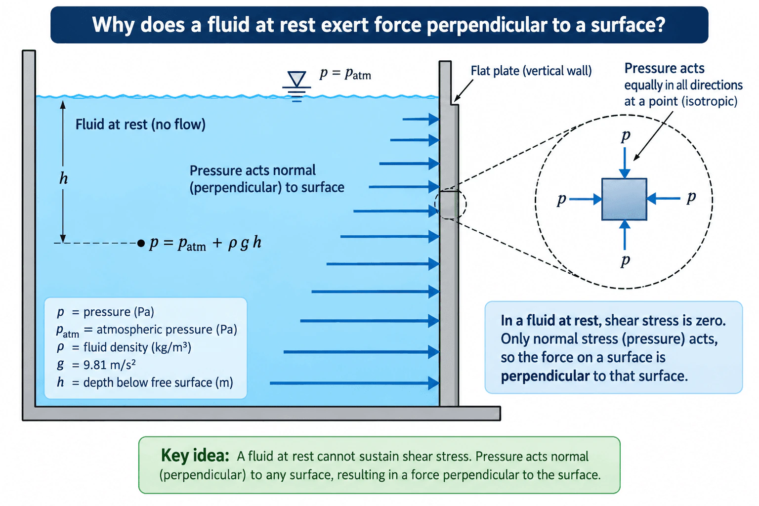
A fluid at rest exerts force perpendicular to a surface because it cannot sustain shear stress in static equilibrium. If a tangential stress remained, the fluid would deform and start moving. Therefore, the stress in a stationary fluid is pressure acting normal to the surface. At a point, static pressure is isotropic, meaning it has the same magnitude in every direction. For a constant-density fluid in an open tank, pressure also increases with depth according to p = p_atm + ρgh.

Detailed Explanation

A fluid at rest has zero shear stress. A fluid continuously deforms when subjected to a sustained shear stress, so a truly static fluid cannot have a tangential stress component. The remaining stress is pressure, and pressure force acts normal, or perpendicular, to the surface it contacts.

At a point in a stationary fluid, pressure is isotropic: its magnitude is the same in every direction. Pressure itself is a scalar quantity. The direction belongs to the force produced by that pressure and is set by the local surface normal.

For a small surface element of area dA, the pressure-force magnitude is

dF = p dA,

where p is pressure in pascals (Pa) and dA is area in square metres (m²). The corresponding force acts perpendicular to that local surface element. For a finite flat surface, the total hydrostatic force is found by integrating the local pressure-force contributions over the area.

The approved diagram uses a stationary, constant-density fluid in an open container under gravity. At the free surface,

p = p_atm,

where p_atm is atmospheric pressure. At a depth h below that surface,

p = p_atm + ρgh,

where ρ is fluid density in kg/m³, g is gravitational acceleration in m/s², and h is depth below the free surface in metres. This expression gives absolute pressure when p_atm is included. The corresponding gauge pressure is

p_gauge = ρgh.

The pressure therefore becomes larger with depth, so the normal force per unit area on the vertical wall also becomes larger with depth. However, the local force direction remains perpendicular to the wall at every depth.

No Bernoulli equation, Reynolds-number correlation, pipe-loss calculation, pump curve, or cavitation check is needed here because the fluid is at rest and there is no flow.

Useful Questions to Ask the Interviewer
  • Are we assuming the fluid is completely at rest and in static equilibrium? This establishes that shear stress is zero.
  • Should pressure be expressed as absolute pressure or gauge pressure? For an open tank, absolute pressure is p_atm + ρgh, while gauge pressure is ρgh.
  • Can the fluid be treated as constant-density? The linear hydrostatic relation p = p_atm + ρgh assumes density is effectively constant over the depth considered.
  • Is the surface flat or curved? Local pressure force is always normal to the surface, but the normal direction changes from point to point on a curved surface.
Why does a fluid at rest exert force perpendicular to a surface? diagram
How to Explain It in an Interview

Start with the physical reason: a fluid at rest cannot sustain shear stress. Any sustained tangential stress would cause continuing deformation and therefore motion, which contradicts static equilibrium. The stress that remains is pressure, which acts normal to the surface.

Then explain isotropy. At a point in a stationary fluid, pressure has the same magnitude in every direction. This is why the diagram shows equal pressure arrows acting toward a small fluid element from different directions.

Next, separate force direction from pressure magnitude. Gravity causes hydrostatic pressure to increase with depth. For the open, constant-density fluid shown, p = p_atm + ρgh. Deeper points therefore exert larger normal forces on the vertical wall, but those forces are still perpendicular to the wall.

Finally, state the limitation: the zero-shear argument applies to a fluid at rest. If the fluid is moving and viscosity is important, tangential viscous shear stresses can also act on a surface.

Technical Approach
  1. Confirm that the fluid is at rest, so the problem is fluid statics.
  2. Apply the static-fluid condition that sustained shear stress is zero.
  3. Treat the remaining stress as scalar pressure acting normal to each local surface element.
  4. If gravity and depth matter, define the reference pressure and use hydrostatic equilibrium. For the open, constant-density case shown, p = p_atm + ρgh.
  5. For a finite surface, integrate the local pressure-force contributions over the area.
  6. Distinguish absolute pressure from gauge pressure and verify that the resulting local force direction is normal to the surface.
Practical Insights

The basic idea is simple because a stationary fluid has no shear stress. The main engineering complication is that pressure may vary over the surface. On a vertical wall, pressure increases with depth, so the pressure-force distribution is not uniform. For a flat wall, all local pressure forces are parallel and combine into one resultant normal force. For a curved surface, every local force is still perpendicular to the local surface, but the normal direction varies, so the vector contributions must be combined. If density varies significantly with elevation or pressure, the simple constant-density relation p = p_atm + ρgh is not sufficient.

Why Interviewers Ask This

Interviewers want to see whether you understand the fundamental stress state in a fluid at rest: a static fluid cannot sustain shear stress, so the remaining stress is pressure acting normal to a surface. They may also expect you to distinguish the direction of pressure force from the separate hydrostatic fact that pressure magnitude increases with depth.

Common interview mistakes

A common mistake is saying that pressure itself has a direction. Pressure is a scalar; the pressure force has a direction set by the local surface normal. Another mistake is assuming pressure is uniform throughout a stationary fluid. Under gravity, pressure generally increases with depth. It is also incorrect to use p = p_atm + ρgh without recognizing the constant-density assumption, or to confuse absolute pressure with gauge pressure. Finally, zero shear stress applies to a fluid at rest; a moving viscous fluid can exert tangential shear stress on a surface.

Interview tip

Lead with the core statement: "A fluid at rest cannot sustain shear stress, so only normal pressure stress remains." Then explain that pressure is isotropic at a point. If needed, use p = p_atm + ρgh to show that depth changes the pressure magnitude while the force direction remains perpendicular to the surface.

Interviewer may ask next
Does p = p_atm + ρgh always apply to a fluid at rest?

No. That form assumes a constant-density fluid under approximately uniform gravitational acceleration, with atmospheric pressure at the reference free surface. More generally, with z positive upward, hydrostatic equilibrium is dp/dz = -ρg. If density varies significantly with elevation or pressure, that differential relation must be integrated using the appropriate density model.

What changes if the fluid is moving instead of at rest?

A moving viscous fluid can develop shear stress, so a surface may experience both normal pressure force and tangential viscous force. The pressure component still acts normal to the surface, but the total fluid force is not necessarily perpendicular because a shear component can act along the surface.

25. Why does rising fountain water spread out while a falling stream from a tap becomes narrower?Fluid Mechanics And Fluid SystemsMedium

Short Interview Answer (30-60 seconds)

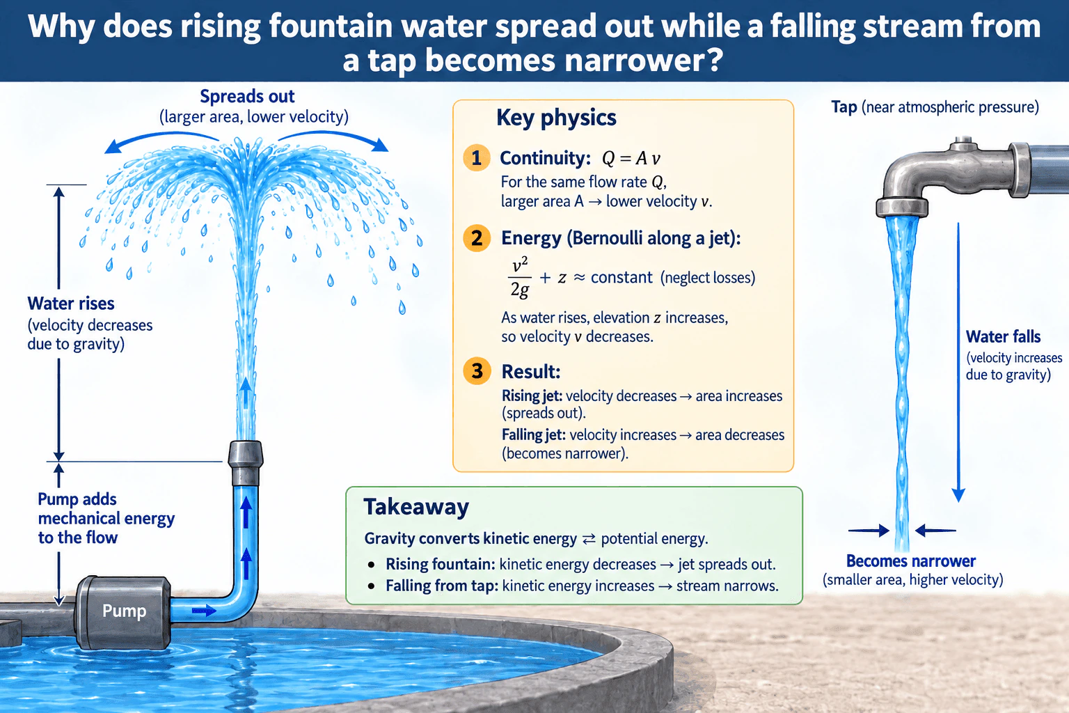
For a steady, incompressible water jet, continuity gives Q = Av. As fountain water rises, gravity slows it, so v decreases. Because the flow rate Q is approximately constant, the cross-sectional area A must increase, which makes the rising jet spread out. Water falling from a tap does the opposite: gravity accelerates it, so v increases and A decreases, making the stream narrower. Along the exposed free jet, pressure is approximately atmospheric, so Bernoulli mainly describes an exchange between velocity head and elevation head.

Detailed Explanation

The key idea is that gravity changes the speed of a free water jet, while conservation of mass links that speed change to the jet's cross-sectional area.

Assume the water is incompressible, the flow is approximately steady, and we are examining the coherent part of the jet before substantial breakup into droplets. The exposed surface is in contact with air, so the static pressure in the free jet is approximately atmospheric. In gauge-pressure terms, p_g ≈ 0.

For steady incompressible flow, continuity gives

Q = Av

where Q is volumetric flow rate in m³/s, A is jet cross-sectional area in m², and v is average jet velocity in m/s. If Q is approximately constant, A and v vary inversely.

For two locations along the same exposed jet, Bernoulli can be simplified to

v²/(2g) + z ≈ constant

when the pressure at both locations is approximately atmospheric and energy losses over the short free-jet distance are neglected. Here g is gravitational acceleration and z is elevation relative to a chosen datum.

For the rising fountain jet, z increases as the water moves upward. Therefore the velocity head v²/(2g) decreases, which means the water slows down. Continuity then requires A to increase, so the coherent jet becomes wider as it rises. Near the highest part of the trajectory, the simple one-dimensional steady-jet model eventually breaks down because the upward velocity becomes very small and the jet loses coherence or breaks into droplets; the real jet does not expand without limit.

For the falling stream from a tap, z decreases as the water moves downward. Gravitational potential energy is converted into kinetic energy, so v increases. With approximately constant Q, continuity requires A to decrease, which makes the falling stream narrower.

The fountain pump adds mechanical energy to the water before it exits the nozzle and establishes the upward flow. Once the water is in the exposed free jet, the local widening is explained primarily by gravity, continuity, and the approximately atmospheric jet pressure. Likewise, the narrowing tap stream is caused by gravitational acceleration after the water leaves the outlet.

Useful Questions to Ask the Interviewer
  • Should I treat the water as incompressible and the flow as steady? For an ordinary fountain or tap stream, that is a reasonable first approximation.
  • Are we considering the coherent portion of the jet before it breaks into droplets? That is the region where the simple Q = Av model applies most directly.
  • Can I take the exposed jet pressure as atmospheric? Yes, approximately, because the free surface is open to the surrounding air.
  • Should I neglect viscosity, air drag, and surface-tension effects for the main explanation? For this conceptual question, yes; those effects mainly influence the detailed jet shape and breakup.
Why does rising fountain water spread out while a falling stream from a tap becomes narrower? diagram
How to Explain It in an Interview

Start with continuity: Q = Av. Then explain what gravity does to velocity. Rising water slows down as elevation increases, so the same flow rate needs a larger cross-sectional area. Falling water speeds up as elevation decreases, so the same flow rate passes through a smaller area. Bernoulli supports the velocity change because pressure is approximately atmospheric along the exposed jet, leaving an exchange mainly between velocity head and elevation head. The opposite-looking jet shapes therefore come from the same two principles: conservation of mass and gravitational energy conversion.

Technical Approach

1. Define the region of interest as the coherent free jet after the water leaves the fountain nozzle or tap. 2. Assume steady, incompressible flow and approximately atmospheric pressure along the exposed jet. 3. Apply continuity, Q = Av, which makes cross-sectional area inversely related to velocity when Q is approximately constant. 4. Apply the free-jet mechanical energy relation, v²/(2g) + z ≈ constant, when pressure terms cancel and short-distance losses are neglected. 5. For rising water, increase z and conclude that v decreases; continuity then requires A to increase. 6. For falling water, decrease z and conclude that v increases; continuity then requires A to decrease. 7. Check the limiting behavior: near the fountain apex, the steady coherent-jet approximation eventually fails as the jet breaks up, so the ideal relation should not be extrapolated to v = 0. 8. Note that viscosity, surface tension, turbulence, and air drag affect the detailed appearance but not the primary continuity-and-gravity explanation.

Practical Insights

The main tradeoff is between a simple ideal free-jet model and the detailed behavior of a real jet. The simple model assumes steady incompressible flow, approximately constant volumetric flow rate, atmospheric pressure along the exposed jet, and negligible losses over the region of interest. Real water jets also experience viscosity, surface tension, turbulence, air drag, and eventual breakup into droplets. Those effects change the detailed shape and limit how close to the fountain apex the simple model can be applied. Pump head, pipe friction, valves, minor losses, the pump curve, the system curve, and cavitation margin can matter when determining the actual fountain flow rate, but they are not required to explain why the exposed jet widens or narrows after leaving the outlet.

Why Interviewers Ask This

This question tests whether the candidate can combine conservation of mass with the mechanical energy equation to explain how gravity changes the velocity and cross-sectional area of a free liquid jet. A strong answer should recognize that water is effectively incompressible, the exposed jet is approximately at atmospheric pressure, and the same steady volumetric flow rate must pass through each coherent cross-section.

Common interview mistakes

A common mistake is to say the rising jet widens because its static pressure increases. In an exposed free jet, the static pressure is approximately atmospheric. Another mistake is to use Bernoulli alone: Bernoulli explains why velocity changes with elevation, while continuity explains why the cross-sectional area changes. It is also incorrect to call the pump's added mechanical energy 'elevation head'; pump head, pressure head, velocity head, and elevation head are distinct energy terms. Finally, do not extrapolate the ideal steady relation all the way to zero velocity at the fountain apex, because the coherent-jet assumption breaks down and the water turns or separates into droplets.

Interview tip

Give the explanation in two linked steps. First state that gravity slows a rising jet and accelerates a falling jet. Then apply Q = Av: lower velocity means a larger area, while higher velocity means a smaller area. Mention that the exposed free jets are approximately at atmospheric pressure. This directly connects the observed shapes to continuity and Bernoulli without introducing unnecessary system details.

Interviewer may ask next
What assumptions are required for using Q = Av and the simplified Bernoulli relation here?

Assume the water is effectively incompressible, the flow is approximately steady, and the jet remains coherent over the region being analyzed. The free surface is exposed to air, so pressure at the compared jet sections is approximately atmospheric. For a short conceptual analysis, viscous losses and air drag can be neglected. Near the fountain apex or after the jet breaks into droplets, the simple one-dimensional steady-jet model becomes less accurate.

If the tap flow rate increases while the outlet area stays the same, how does that affect the falling stream?

With the same outlet area A0, a larger flow rate Q means a larger initial outlet velocity v0 = Q/A0. After the water falls through a vertical distance Δz, an ideal free-jet estimate gives v = √(v0² + 2gΔz). Continuity then gives A = Q/v = A0v0/v. The stream still narrows as it falls because v increases, but a larger initial velocity makes the fractional contraction over the same drop smaller, and the absolute stream area at that location is larger than it would be for the lower-flow case.

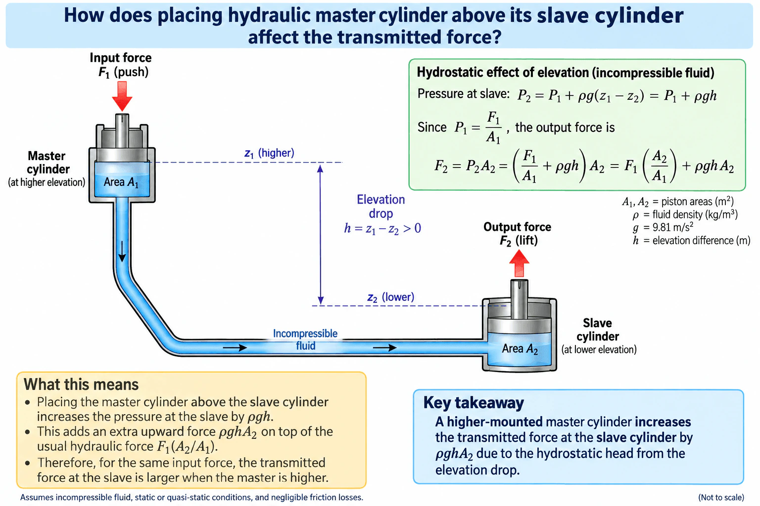
26. How does placing a hydraulic master cylinder above its slave cylinder affect the transmitted force?Fluid Mechanics And Fluid SystemsMedium

Short Interview Answer (30-60 seconds)

If the master cylinder is above the slave cylinder, the lower slave sees extra hydrostatic pressure because it is at a lower elevation in the same incompressible fluid. Under static or quasi-static conditions with negligible line losses, the pressure at the slave is P2 = P1 + ρgh, where h = z1 - z2 > 0. Since P1 = F1/A1, the transmitted slave force becomes F2 = P2A2 = F1(A2/A1) + ρghA2. So, for the same input force and piston areas, placing the master above the slave slightly increases the transmitted force.

Detailed Explanation

In a hydraulic system, force transmission comes from pressure acting on piston area, but elevation also matters because fluid pressure increases with depth. If the master cylinder is mounted above the slave cylinder, the slave is at a lower elevation and therefore receives additional hydrostatic pressure.

Define the symbols first:

  • F1 = input force applied to the master piston
  • A1 = master-piston area
  • A2 = slave-piston area
  • P1 = pressure created at the master cylinder
  • P2 = pressure at the slave cylinder
  • z1 = elevation of the master piston center
  • z2 = elevation of the slave piston center
  • h = z1 - z2, so h > 0 when the master is above the slave
  • ρ = fluid density
  • g = gravitational acceleration

For an incompressible hydraulic fluid under static or quasi-static conditions, the master creates pressure

P1 = F1 / A1

Because the slave is lower, hydrostatic head increases the pressure there:

P2 = P1 + ρg(z1 - z2) = P1 + ρgh

The output force at the slave is then

F2 = P2A2 = (F1 / A1 + ρgh)A2

which can also be written as

F2 = F1(A2 / A1) + ρghA2

This shows two parts of the transmitted force:

  1. F1(A2 / A1), which is the usual hydraulic force multiplication from the piston-area ratio.
  2. ρghA2, which is the extra force caused by the slave being lower than the master.

So the direct answer is: placing the master cylinder above the slave cylinder increases the transmitted force at the slave, assuming the fluid is incompressible and the system is static or moving slowly enough that losses are negligible.

In a real system with appreciable flow, pressure losses in the line, bends, fittings, or valves reduce the pressure available at the slave. In that case, a more realistic relation is

P2 ≈ P1 + ρgh - ΔPloss

So the hydrostatic effect still increases slave pressure, but the net transmitted force depends on both elevation gain and flow losses.

For pressure reference, gauge pressure is usually sufficient here because the same atmosphere acts on the system and cancels when comparing pressures. Absolute pressure becomes important only if you are checking things such as vapor pressure or cavitation.

Validation is straightforward:

  • Check the sign of h. If the master is above the slave, h must be positive.
  • Check units. ρgh has units of pressure.
  • Check the limiting case. If z1 = z2, then h = 0 and the extra hydrostatic term disappears.
  • Check physical meaning. A lower slave in a connected liquid should have higher pressure.

The main limitation is that this is an educational hydraulic model. Real designs may also need seal friction, line expansion, trapped air, transient response, and detailed loss calculations.

Useful Questions to Ask the Interviewer
  • Should I assume the hydraulic fluid is incompressible and the system is static or quasi-static?
  • Do you want me to neglect line, fitting, and valve pressure losses?
  • Should I express pressure as gauge pressure?
  • Are the master and slave piston areas known, or do you only want the qualitative effect of elevation?
  • Should the elevation difference be measured between piston centers?
How does placing a hydraulic master cylinder above its slave cylinder affect the transmitted force? diagram
How to Explain It in an Interview

Start with the physical idea: pressure in a connected liquid increases as you move downward. If the master cylinder is above the slave cylinder, the slave sits at a lower elevation, so it receives extra pressure from hydrostatic head.

Then write the two key steps. First, the master creates pressure P1 = F1 / A1. Second, the lower slave sees P2 = P1 + ρgh. Multiplying by the slave area gives F2 = P2A2 = F1(A2 / A1) + ρghA2.

Finish with the conclusion: for the same input force, the slave force is slightly larger when the master is above the slave. Then mention the assumptions: incompressible fluid, static or quasi-static conditions, and negligible friction losses. If the system has significant flow, add that line losses reduce the net pressure reaching the slave.

Technical Approach
  1. Define the reference elevations z1 and z2, then compute h = z1 - z2.
  2. State the assumptions: incompressible fluid, static or quasi-static behavior, and negligible line losses for the ideal case.
  3. Compute the master-cylinder pressure as P1 = F1 / A1.
  4. Apply the hydrostatic pressure relation to the lower slave: P2 = P1 + ρgh.
  5. Convert pressure at the slave into output force using F2 = P2A2.
  6. Rearrange the result as F2 = F1(A2 / A1) + ρghA2.
  7. If the problem includes motion or flow, adjust the slave pressure to P2 ≈ P1 + ρgh - ΔPloss.
  8. Check the sign convention, units, and limiting case h = 0.
Practical Insights

The main tradeoff is simple: the hydrostatic benefit increases with fluid density, elevation drop, and slave area, but real systems also lose pressure through tubing, bends, fittings, and valves when fluid is moving. Longer lines, smaller diameters, higher flow rates, or more viscous fluid increase those losses. So the pure elevation effect is easy to calculate, but the real transmitted force may be lower than the ideal value once flow losses and system compliance are included.

Why Interviewers Ask This

This question tests whether the candidate can combine basic hydraulics with fluid statics. Interviewers want to see if you know that piston-area force transmission is not the only effect in a hydraulic line: elevation also changes pressure through hydrostatic head. A strong answer should state the assumptions, write the pressure relation correctly, and explain how the extra pressure changes the slave-cylinder force.

Common interview mistakes

Common mistakes include ignoring elevation entirely, saying pressure is identical everywhere in the fluid without considering hydrostatic head, using the wrong sign for the elevation term, forgetting that the extra force is ρghA2, confusing gauge pressure with absolute pressure, and applying the ideal static result even when significant flow losses are present.

Interview tip

Give the conclusion first: a lower slave cylinder gets extra hydrostatic pressure, so the transmitted force increases. Then write P2 = P1 + ρgh and F2 = P2A2. That shows both the physics and the force effect clearly. End by stating the assumptions and mentioning that real line losses reduce the net pressure in a moving system.

Interviewer may ask next
How would you validate this assumption set in a real hydraulic system?

I would first confirm that the fluid can be treated as incompressible and that the operating condition is static or slow enough for hydrostatics to dominate. Then I would measure or estimate the elevation difference between the piston centers, verify piston areas, and calculate the ideal pressure increase ρgh. Next, I would check whether expected flow rates are large enough to create meaningful pressure losses in the tubing and fittings. If needed, I would compare measured slave pressure or output force against the ideal value to see whether friction losses, trapped air, seal drag, or line compliance are significant.

What changes if the slave cylinder is above the master cylinder instead?

The hydrostatic term changes sign because the slave is now at a higher elevation. In that case, the pressure at the slave is lower than the pressure at the master by about ρgh, so the force becomes F2 = (P1 - ρgh)A2 = F1(A2 / A1) - ρghA2, neglecting losses. So raising the slave above the master slightly reduces the transmitted force for the same input force.

27. How do you account for water hammer when designing a fluid system?Fluid Mechanics And Fluid SystemsHard

Short Interview Answer (30-60 seconds)

I account for water hammer by treating rapid changes in flow as a transient event. I first identify cases such as fast valve closure, pump trip, pump startup, check-valve slam, or sudden demand changes. For a first estimate, I use the Joukowsky relation, ΔP = ρaΔV, where ρ is fluid density, a is pressure-wave speed, and ΔV is the velocity change. I compare the event duration with the characteristic round-trip wave time, 2L/a, and check both maximum and minimum transient pressures. I then reduce the surge using measures such as controlled valve motion, pump ramping, appropriate check valves, surge vessels, accumulators, or other transient-control devices. For important systems, I confirm the design with a transient hydraulic model rather than relying only on a simplified equation.

Detailed Explanation

Water hammer occurs when liquid velocity changes rapidly enough that a pressure disturbance travels through the piping as a wave. A normal steady-state calculation using the Bernoulli equation and Darcy-Weisbach losses is not sufficient because, during the transient, pressure and flow vary with both time and position.

I would first establish the normal operating condition. That includes the fluid properties, pipe length and diameter, flow rate, average velocity, elevations, steady pressure losses, valve positions, pump operating point, and the pressure reference being used. Gauge pressure is useful for many equipment checks, but absolute pressure must be used when evaluating vapor formation, cavitation, or column separation.

For steady liquid flow, the fluid is often treated as nearly incompressible. Water-hammer analysis, however, must account for the finite compressibility of the liquid and the elasticity of the pipe because together they determine the pressure-wave speed.

For an initial estimate of a rapid velocity change, I use the Joukowsky relation:

ΔP = ρaΔV

where:

  • ΔP = transient pressure change
  • ρ = liquid density
  • a = pressure-wave speed
  • ΔV = change in average liquid velocity

The equivalent change in pressure head is:

ΔH = aΔV / g

where g is gravitational acceleration.

This is a screening relation for a sufficiently rapid change in velocity. It should not automatically be applied as the final answer for every valve or pump transient.

The next important check is the wave travel time. For a simple line of length L, the characteristic round-trip time is approximately:

tw = 2L / a

I compare the actual valve-closing time, pump rundown time, or other event duration with this characteristic time. If the flow change occurs very rapidly relative to the wave travel time, the transient can approach the full Joukowsky pressure change. If the velocity changes more gradually, the peak surge is generally lower and depends on the actual time history of the event and the system boundaries.

I then evaluate the credible transient scenarios rather than only one nominal case. Typical cases include rapid valve closure, rapid valve opening, pump trip after loss of power, pump startup, check-valve closure, sudden downstream demand changes, and combinations of equipment actions.

I check both positive and negative transient pressures. High pressure can overstress pipes, fittings, valves, joints, gaskets, supports, and connected equipment. Low absolute pressure can cause local vapor formation, cavitation, or liquid-column separation. If separated liquid columns subsequently recombine, the resulting pressure spike can be more severe than the initial event.

Mitigation should address the physical source of the transient where practical. If valve motion is too fast, I can increase the actuation time or use a controlled closing profile. Pump acceleration and deceleration can be controlled with suitable drives or operating logic. Check valves can be selected and located to reduce reverse velocity and slam. Surge vessels, hydropneumatic tanks, accumulators, or air chambers can temporarily absorb or supply liquid. Depending on the application, bypasses or appropriately engineered pressure-relief devices may also help manage a transient.

Pipe sizing can influence the problem as well. For a given volumetric flow rate, increasing pipe diameter lowers average velocity, so the associated velocity change may be smaller. However, changing diameter also changes cost, friction losses, system dynamics, and sometimes wave behavior, so it should be evaluated as part of the whole design rather than as an isolated fix.

For a long, branched, high-energy, or otherwise important piping system, I would use a transient hydraulic model based on conservation of mass and momentum. The model should represent pipe lengths and elevations, realistic pressure-wave speeds, friction, valve motion versus time, pump characteristics and rotational inertia where relevant, check-valve behavior, reservoirs or pressure boundaries, and any surge-control devices. I would examine pressure and flow histories at multiple locations because the largest pressure excursion may not occur where the initiating event happens.

I would also evaluate the pump suction side where applicable. A transient pressure decrease can reduce the available absolute suction pressure and therefore reduce cavitation margin. The relevant check must use absolute pressure and the applicable vapor-pressure and NPSH criteria rather than gauge pressure alone.

Validation matters because transient results can be sensitive to uncertain inputs such as actual valve stroke characteristics, pump inertia, check-valve response, pipe restraint, pipe-wall properties, fluid properties, entrained gas, and boundary conditions. I would compare model inputs with drawings, specifications, and manufacturer data, perform sensitivity checks on important uncertain parameters, and, when practical, compare predicted pressure histories with commissioning or field pressure measurements.

The design conclusion should therefore be based on credible transient cases, allowable maximum and minimum pressures, suitable mitigation, and validated model assumptions. A single simplified Joukowsky calculation is useful for screening, but it does not by itself demonstrate that the complete fluid system is acceptable.

Useful Questions to Ask the Interviewer
  • What event is expected to cause the transient: valve closure, pump trip, pump startup, check-valve action, or another operating change?
  • What are the pipe length, diameter, material, wall thickness, and restraint conditions?
  • What are the normal flow rate, velocity, fluid density, and operating pressures?
  • How quickly does the valve, pump, or other device change the flow?
  • What are the allowable maximum and minimum pressures for the pipe and connected equipment?
  • Are there high points, major elevation changes, long transmission lines, or locations where low absolute pressure could cause vapor formation or column separation?
  • Are surge vessels, accumulators, controlled valves, variable-speed drives, or other transient-control devices available?
How to Explain It in an Interview

I would explain that I first identify the fastest credible change in flow and establish the initial velocity and pressure. I use ΔP = ρaΔV as a screening estimate and compare the event duration with the characteristic wave time 2L/a. Then I check both the maximum pressure and the minimum absolute pressure because water hammer can cause overpressure as well as cavitation or column separation. I reduce the transient at its source where possible, for example through controlled valve motion, pump ramping, or better check-valve behavior, and add surge-control hardware when needed. For a long, complex, or critical system, I would verify the final design using a transient hydraulic model with realistic pipe, pump, valve, elevation, and boundary-condition behavior, then validate the important assumptions against manufacturer information and measurements where practical.

Technical Approach
  1. Define the normal operating state: fluid density, viscosity, flow rate, pipe geometry, elevations, steady pressures, major and minor losses, valve positions, and pump operating point.
  2. Identify credible rapid-flow events such as valve closure, valve opening, pump trip, pump startup, check-valve closure, and sudden demand changes.
  3. Calculate the initial average velocity from V = Q/A at relevant pipe sections.
  4. Determine or estimate the pressure-wave speed a using appropriate fluid compressibility, pipe-wall elasticity, geometry, and restraint assumptions, or validated engineering data.
  5. Estimate the rapid-transient pressure change using ΔP = ρaΔV and the corresponding head change ΔH = aΔV/g.
  6. Calculate the characteristic round-trip wave time tw = 2L/a for the relevant line and compare it with the actual duration of the flow-changing event.
  7. Check maximum transient pressure against allowable pressure limits for the pipe, fittings, valves, pumps, joints, and connected equipment.
  8. Check minimum absolute pressure against vapor-pressure, cavitation, column-separation, and pump-suction requirements where applicable.
  9. Evaluate mitigation options that reduce the velocity-change rate or absorb transient flow, such as controlled valve motion, pump ramping, suitable check valves, surge vessels, accumulators, air chambers, bypasses, or appropriately engineered relief devices.
  10. For important or complex systems, perform a transient hydraulic simulation using realistic pipe wave speeds, friction, elevations, pump behavior, valve motion, check-valve dynamics, boundary conditions, and surge-control devices.
  11. Test credible operating combinations and perform sensitivity checks on uncertain parameters.
  12. Validate important inputs against drawings, specifications, and manufacturer data and, where practical, compare predictions with commissioning or field pressure measurements before final acceptance.
Practical Insights

The main tradeoff is between reducing transient pressure and adding cost, response time, equipment, space, and control complexity. Slowing a valve is often simple, but the process may require rapid isolation. Controlled pump acceleration or deceleration can reduce velocity changes, but it depends on the pump, drive, process, and failure mode. A surge vessel or accumulator can strongly reduce pressure swings but adds footprint, maintenance, and operating requirements. Increasing pipe diameter lowers velocity for a given flow rate and can reduce surge severity, but it increases capital cost and changes steady-state and transient behavior. A Joukowsky calculation is fast and useful for screening, while a detailed transient model requires more reliable input data and engineering effort but can represent wave reflections, valve characteristics, pump inertia, branches, cavitation, and surge-control devices.

Why Interviewers Ask This

Interviewers want to see whether you recognize water hammer as a transient pressure problem rather than a steady-state pressure-drop problem. They are evaluating whether you can identify rapid flow changes, estimate pressure-wave magnitude and timing, recognize both overpressure and low-pressure risks, select practical mitigation measures, and validate that the piping, valves, pumps, supports, and connected equipment remain within acceptable operating limits.

Common interview mistakes

Common mistakes include treating water hammer as a steady-state pressure-drop problem; using ideal Bernoulli or normal friction losses alone to estimate the surge; applying ΔP = ρaΔV without checking whether the velocity change is sufficiently rapid; assuming pressure-wave speed without considering fluid compressibility and pipe elasticity; checking only maximum pressure and ignoring minimum absolute pressure, cavitation, or column separation; considering only total valve stroke time instead of the actual valve motion and flow-change profile; ignoring pump inertia and check-valve dynamics; checking pressure at only the initiating location; mixing gauge and absolute pressure; and assuming a simplified equation or unvalidated simulation proves the real system is acceptable.

Interview tip

Organize the answer around four steps: identify the transient event, estimate its pressure-wave magnitude and timing, check both high and low pressure limits, and then mitigate and validate. Explicitly mentioning wave travel time, minimum absolute pressure, and transient-model validation demonstrates stronger engineering judgment than discussing only pipe overpressure.

Interviewer may ask next
What assumptions would you verify before trusting a Joukowsky water-hammer calculation?

I would verify the initial flow and velocity, expected ΔV, liquid density, effective pressure-wave speed, and whether the velocity change is rapid enough for the Joukowsky relation to represent the event. I would also check the pipe material, wall thickness, restraint assumptions, liquid compressibility, actual valve motion versus time, pump inertia, check-valve behavior, elevations, and boundary conditions. If low pressure is possible, I would evaluate minimum absolute pressure rather than gauge pressure alone. For a complex or important network, I would use these verified inputs in a transient hydraulic model and compare the model with manufacturer data or measured pressure traces where available.

How would your design approach change if the process requires a valve to close very quickly and you cannot simply increase its closing time?

If fast closure is a process requirement, I would focus on controlling the resulting transient instead of relying on slower overall closure. I would quantify the expected surge and evaluate options such as a surge vessel, hydropneumatic accumulator, bypass, appropriately engineered relief device, or a tailored valve-motion profile that changes the most hydraulically sensitive portion of the stroke more gradually while still meeting the required isolation time. I would also review pipe diameter, allowable pressure limits, supports, pump behavior, and check-valve dynamics. Because the severe transient source remains in the system, I would verify the selected mitigation with a detailed transient hydraulic model across the credible operating range.

28. What upper-surface airspeeds provide the specified wing lift?Fluid Mechanics And Fluid SystemsHard

Question Details

Use the approximate Bernoulli model for 1000 N of lift per m² of wing area. Calculate upper-surface speed for: (a) lower-surface speed 60.0 m/s and air density 1.29 kg/m³; (b) lower-surface speed 245 m/s and density one-quarter as large.

Short Interview Answer (30-60 seconds)

The specified lift per unit area is 1000 N/m², which corresponds to a 1000 Pa lower-to-upper surface pressure difference in the requested approximate model. Using Δp = (1/2)ρ(V_upper² - V_lower²), the required upper-surface speed is V_upper = √(V_lower² + 2Δp/ρ). For (a), V_lower = 60.0 m/s and ρ = 1.29 kg/m³ give V_upper ≈ 71.8 m/s. For (b), ρ = 1.29/4 = 0.3225 kg/m³ and V_lower = 245 m/s give V_upper ≈ 257 m/s. The second result is only an approximate incompressible-Bernoulli result because compressibility is important at such a high airspeed.

Detailed Explanation

The specified lift loading can be represented, in this simplified Bernoulli model, as a pressure difference between the lower and upper wing surfaces. Therefore,

Δp = p_lower - p_upper = 1000 N/m² = 1000 Pa.

Assume steady flow, negligible elevation difference between the representative upper- and lower-surface locations, and the same upstream total pressure for the two representative flow paths. Neglect viscous losses and treat density as constant because the problem specifically requests the approximate Bernoulli model.

For each representative flow path,

p + (1/2)ρV² = constant.

Comparing the lower and upper surface locations under these assumptions gives

p_lower + (1/2)ρV_lower² = p_upper + (1/2)ρV_upper².

Therefore,

Δp = p_lower - p_upper = (1/2)ρ(V_upper² - V_lower²).

Solving for the unknown upper-surface speed,

V_upper = √(V_lower² + 2Δp/ρ).

Here:

  • V_lower is the lower-surface airspeed.
  • V_upper is the required upper-surface airspeed.
  • ρ is the air density.
  • Δp is the required lower-to-upper pressure difference of 1000 Pa.

For part (a):

V_lower = 60.0 m/s ρ = 1.29 kg/m³ Δp = 1000 Pa

V_upper = √[(60.0 m/s)² + 2(1000 Pa)/(1.29 kg/m³)]

= √(3600 + 1550.39) m²/s²

= √5150.39 m²/s²

≈ 71.8 m/s.

So the required upper-surface airspeed for part (a) is approximately 71.8 m/s.

For part (b), the density is one-quarter of the value in part (a):

ρ = 1.29/4 = 0.3225 kg/m³.

With V_lower = 245 m/s,

V_upper = √[(245 m/s)² + 2(1000 Pa)/(0.3225 kg/m³)]

= √(60025 + 6201.55) m²/s²

= √66226.55 m²/s²

≈ 257.3 m/s.

So the required upper-surface airspeed for part (b) is approximately 257 m/s to three significant figures.

The units are consistent because pressure divided by density has units

(Pa)/(kg/m³) = (kg/(m·s²))/(kg/m³) = m²/s²,

which matches velocity squared.

A physical check also makes sense: in this simplified model the upper-surface static pressure must be lower than the lower-surface pressure to produce upward lift, so V_upper must be greater than V_lower. Both calculated results satisfy that condition.

The major limitation is compressibility. The first case is a relatively low-speed airflow for which constant-density Bernoulli is a reasonable introductory approximation. Speeds around 245–257 m/s, however, correspond to a substantial fraction of the local speed of sound under ordinary atmospheric conditions, so density changes can no longer be assumed negligible. A real analysis of the second case would require compressible aerodynamics and the actual wing pressure distribution. The value of about 257 m/s is therefore the answer to the requested approximate Bernoulli calculation, not a complete aerodynamic prediction.

Useful Questions to Ask the Interviewer
  • Should I interpret the specified 1000 N/m² lift as a uniform 1000 Pa pressure difference between the lower and upper surfaces for this simplified calculation?
  • Should I use the incompressible Bernoulli model even in the 245 m/s case and then state compressibility as a limitation?
  • May I neglect the elevation difference between the representative upper- and lower-surface locations?
How to Explain It in an Interview

I would first convert the lift per unit area into a pressure difference: 1000 N/m² equals 1000 Pa. Then I would use the simplified Bernoulli relation Δp = (1/2)ρ(V_upper² - V_lower²) and solve for V_upper. For the first case, that gives about 71.8 m/s. For the second case, the density is reduced to 0.3225 kg/m³, which gives about 257 m/s. I would also point out that the upper-surface speed is greater than the lower-surface speed in both cases, which is consistent with lower static pressure above the wing in this simplified model. Finally, I would flag that the second case is too fast for incompressible Bernoulli to be a high-accuracy aerodynamic model, so a real design analysis would use compressible-flow methods.

Technical Approach
  1. Convert the specified lift per unit area into the required pressure difference: Δp = L/A = 1000 Pa.
  2. State the assumptions: steady flow, negligible elevation difference, common upstream total pressure for the representative flow paths, negligible viscous losses, and constant density as required by the approximate Bernoulli model.
  3. Write Δp = (1/2)ρ(V_upper² - V_lower²).
  4. Rearrange to V_upper = √(V_lower² + 2Δp/ρ).
  5. For part (a), substitute V_lower = 60.0 m/s and ρ = 1.29 kg/m³ to obtain V_upper ≈ 71.8 m/s.
  6. For part (b), calculate ρ = 1.29/4 = 0.3225 kg/m³, then substitute V_lower = 245 m/s to obtain V_upper ≈ 257.3 m/s.
  7. Check units and confirm that V_upper > V_lower, which is physically consistent with lower static pressure on the upper surface in this simplified model.
  8. Flag compressibility as the main limitation of the second calculation.
Practical Insights

The numerical calculation is straightforward, but choosing and judging the model is the important engineering part. For the same required 1000 Pa pressure difference, a lower air density requires a larger difference in velocity squared. The main tradeoff is simplicity versus physical accuracy: constant-density Bernoulli is useful for a quick low-speed estimate, while high-speed airflow requires compressible-flow analysis for better accuracy.

Why Interviewers Ask This

This tests whether the candidate can convert lift per unit area into a pressure difference, apply the simplified Bernoulli model with consistent assumptions and units, solve correctly for an unknown airspeed, and recognize when compressibility limits the model.

Common interview mistakes

Common mistakes include treating 1000 N/m² as a total force instead of recognizing that it is equivalent to a 1000 Pa pressure difference, reversing the pressure-difference sign, using V_lower² - V_upper² instead of V_upper² - V_lower², forgetting the factor of 2 when rearranging Bernoulli's equation, failing to reduce the density to 0.3225 kg/m³ in part (b), mixing units, or reporting the high-speed result without noting the limits of the incompressible model.

Interview tip

Start by stating that 1000 N/m² equals a 1000 Pa pressure difference, derive the upper-speed equation before substituting numbers, and perform a physical check that V_upper is greater than V_lower. For the second case, explicitly identify compressibility as a limitation. That demonstrates both calculation skill and engineering judgment.

Interviewer may ask next
How would you check whether treating the airflow as incompressible is reasonable?

Estimate the Mach number M = V/a using the local speed of sound a. As a common engineering guideline, density changes are often small enough for an incompressible approximation below roughly Mach 0.3. The 60–72 m/s case is comparatively low speed and is much closer to that regime. The 245–257 m/s case is a substantial fraction of the speed of sound and therefore requires a compressibility check and, for accurate analysis, compressible-flow equations. The exact Mach number depends on the local speed of sound, which depends mainly on air temperature.

If the air density decreases while the required lift per unit area and lower-surface speed remain unchanged, what happens to the required upper-surface speed?

It increases. From V_upper² = V_lower² + 2Δp/ρ, reducing ρ increases the term 2Δp/ρ, so a larger upper-surface velocity is required to create the same pressure difference in this simplified model. If the required speed becomes high enough, however, the constant-density Bernoulli assumption becomes inaccurate and a compressible-flow model should be used.

29. What is a hazard-control program?SafetyEasy

Short Interview Answer (30-60 seconds)

A hazard-control program is a structured process for identifying workplace or equipment hazards, assessing the associated risk, and putting controls in place to reduce that risk to an acceptable level. It should follow the hierarchy of controls, giving priority to elimination, substitution, and engineering controls before relying on administrative controls or personal protective equipment. The program also includes verification, documentation, training where applicable, and periodic review so controls remain effective as equipment or conditions change.

Detailed Explanation

A hazard-control program is an organized process for preventing injuries, equipment damage, and unsafe operating conditions before they lead to an incident. The basic idea is to identify what can cause harm, understand how people or equipment could be exposed, reduce the risk using appropriate controls, and verify that those controls remain effective.

For a mechanical engineer, hazards may include rotating equipment, pinch points, hot surfaces, pressurized systems, suspended loads, gravity, springs, electrical energy associated with machinery, and other forms of stored energy. The program should not assume that personal protective equipment alone makes these hazards acceptable. The preferred approach is to apply the hierarchy of controls: eliminate the hazard where practical, substitute a less hazardous method or material, use engineering controls such as guards or interlocks, add administrative controls such as procedures and training, and use personal protective equipment for remaining exposure where required.

A practical hazard-control program normally includes hazard identification, risk assessment, control selection, implementation, verification, documentation, and review. Methods such as a job hazard analysis, machinery risk assessment, or failure mode and effects analysis can help identify credible hazards and failure conditions. During maintenance, stored energy should be identified and controlled through the applicable authorized isolation and verification procedure, such as lockout/tagout where required. Guards and interlocks should be verified before operation, and an immediate uncontrolled hazard should result in stopping work and escalating within the worker's authority.

The program should also address residual risk. A control may reduce risk without eliminating it completely, so the remaining risk, operating limitations, inspection needs, and required procedures should be documented. Changes to equipment, tooling, materials, software, production rate, maintenance methods, or operating conditions should trigger a review because they can introduce new hazards or reduce the effectiveness of existing controls.

Useful Questions to Ask the Interviewer
  • What equipment, machine, or process is being evaluated?
  • Who could be exposed to the hazard, and during which operating, setup, cleaning, troubleshooting, or maintenance conditions?
  • What types of stored energy are present, such as electrical, pressure, thermal, gravity, spring, or rotating energy?
  • What guards, interlocks, emergency stops, procedures, or isolation requirements already exist?
  • What jurisdiction, equipment rules, or company procedures apply?
  • Have there been incidents, near misses, maintenance findings, or process changes that should be considered?
  • How will the effectiveness of the selected controls be verified and maintained?

These questions define the physical and operational boundaries of the assessment. They also prevent an engineer from assuming that a control effective during normal production is automatically effective during maintenance, fault recovery, or other non-routine work.

How to Explain It in an Interview

I would explain that I treat hazard control as a continuous engineering process. First, I define the equipment or activity and identify credible hazards, including mechanical motion, pressure, temperature, gravity, springs, electrical sources, and other stored energy. Next, I assess the risk by considering the severity of possible harm and the likelihood or opportunity for exposure.

Then I apply the hierarchy of controls. I first ask whether the hazard can be eliminated or reduced at the source. If not, I consider substitution and engineering controls such as fixed guards, barriers, interlocks, pressure-relief features, or design changes. Administrative controls and personal protective equipment are added where necessary, but I would not use them as substitutes for feasible engineering controls.

After implementation, I verify that the controls work under the relevant operating and maintenance conditions. For example, I would confirm that guards and interlocks function as intended and that hazardous stored energy can be isolated and verified before maintenance. I would document any residual risk and the conditions required for safe use.

Finally, I would review the controls after incidents, near misses, equipment modifications, process changes, or evidence that a control is not performing as intended. The important point is that a hazard-control program is not just a checklist; it is a repeatable process for identifying risk, reducing it at the source where possible, validating the controls, and maintaining them throughout the equipment or process life cycle.

Technical Approach
  1. Define the equipment, task, operating modes, maintenance activities, and people who could be exposed.
  2. Identify hazards, including rotating parts, pinch points, hot surfaces, pressure, lifting, gravity, springs, electrical sources, and other stored energy as applicable.
  3. Assess the risk associated with each credible hazard using the applicable organizational or jurisdictional method.
  4. Apply the hierarchy of controls, prioritizing elimination, substitution, and engineering controls before administrative controls and personal protective equipment.
  5. Implement the selected controls without bypassing required guards, interlocks, or authorized isolation procedures.
  6. Verify that the controls work under normal, abnormal, setup, and maintenance conditions that are within scope.
  7. Document residual risk, required procedures, inspection or maintenance needs, and any limitations.
  8. Train affected personnel where required by the applicable procedure or program.
  9. Review the hazard assessment and controls after incidents, near misses, equipment changes, process changes, or evidence that a control is no longer effective.
Practical Insights

The main tradeoff is balancing effective risk reduction with practical operation, maintenance, reliability, and access. Engineering controls generally reduce dependence on human behavior, but they must be designed so they do not introduce new hazards or encourage bypassing. Administrative controls and PPE may be easier to add, but they depend more heavily on consistent human action. The effort required for the program increases with equipment complexity, the number of operating modes, stored-energy sources, maintenance tasks, and frequency of change.

Why Interviewers Ask This

Interviewers ask this to evaluate whether you understand safety as a systematic engineering process rather than a one-time reaction to an incident. They want to see that you can identify hazards, assess risk, apply the hierarchy of controls, verify that controls work, document residual risk, and update controls when equipment, processes, or operating conditions change.

Common interview mistakes

Common mistakes include treating PPE as the first or only control, evaluating only normal operation while ignoring setup and maintenance, failing to identify stored energy, assuming an emergency stop is a substitute for energy isolation, bypassing or defeating guards and interlocks, implementing a control without verifying its effectiveness, failing to document residual risk, and not reassessing hazards after equipment or process changes.

Interview tip

Keep the answer structured around identify, assess, control, verify, and review. Mention the hierarchy of controls and emphasize that engineering controls are preferred over relying on PPE. A strong safety answer also recognizes stored energy, maintenance conditions, residual risk, and the need to stop and escalate when an immediate uncontrolled hazard exists.

Interviewer may ask next
How would you verify that a hazard control is actually effective?

I would define what successful risk reduction should look like before implementation and then verify the control under the relevant operating conditions. That may include inspecting guards, testing interlocks or emergency-stop functions according to applicable procedures, confirming that hazardous energy can be isolated and verified before maintenance, observing whether the control prevents exposure to the hazard, and reviewing whether any new hazards were introduced. I would document the results and any residual risk. If verification shows that the control does not adequately reduce risk, I would revise the design or add stronger controls rather than assuming the original measure is sufficient.

What should happen if a process changes after the original hazard controls were approved?

The hazard assessment should be reviewed through the applicable change-management process because a change can introduce new hazards or make existing controls ineffective. I would evaluate what changed, identify any new exposure or stored-energy conditions, reassess the affected risks, and update the controls using the hierarchy of controls. The revised controls should then be verified before relying on them, and any affected procedures, documentation, inspection requirements, or training should be updated as appropriate.

30. What does de-energizing equipment mean?SafetyEasy

Short Interview Answer (30-60 seconds)

De-energizing equipment means disconnecting or isolating it from hazardous energy sources and controlling any stored or residual energy so the equipment cannot unexpectedly start, move, pressurize, heat, or release energy during servicing. It is more than pressing the Stop button. The relevant energy sources must be isolated, stored energy must be released or restrained, and the safe condition must be verified according to the applicable authorized procedure before work begins.

Detailed Explanation

De-energizing equipment means putting it into a condition where hazardous energy has been removed, isolated, dissipated, or otherwise controlled so it cannot unexpectedly harm someone during maintenance or servicing.

The important distinction is that stopping a machine is not necessarily the same as de-energizing it. A control button may stop normal operation while electrical power, hydraulic pressure, pneumatic pressure, gravitational potential energy, spring force, thermal energy, or rotating inertia is still present.

For example, switching off a hydraulic press may stop its motor, but trapped hydraulic pressure could still move an actuator. A raised machine component may still fall under gravity after electrical power is disconnected. A rotating component may continue moving because of inertia. Those hazards must also be controlled.

A proper de-energization process therefore begins by identifying every hazardous energy source associated with the equipment and the intended work. The equipment is normally shut down, its hazardous energy sources are isolated using appropriate energy-isolating devices, and stored energy is relieved, discharged, blocked, restrained, or otherwise controlled as appropriate. Where required, the applicable lockout/tagout procedure is then used to maintain that isolation.

Verification is essential. A switch or valve position alone does not prove that hazardous energy is absent. Isolation can be incomplete, a device can be mislabeled, pressure can remain trapped, or another energy source can still be connected. The authorized verification method should therefore be completed before work begins.

Useful Questions to Ask the Interviewer
  • What types of hazardous energy are present on this equipment?
  • Is there stored hydraulic, pneumatic, gravitational, spring, thermal, or rotational energy after shutdown?
  • What authorized energy-isolation or lockout/tagout procedure applies to this equipment?
  • Are there multiple isolation points, interconnected machines, or multiple workers involved?
  • What verification method is required before servicing begins?

These questions help define the actual hazards because de-energization is equipment-specific. I would not assume that disconnecting electrical power alone controls every possible energy source.

How to Explain It in an Interview

I would explain that de-energizing equipment means controlling all hazardous energy so the machine cannot unexpectedly start, move, pressurize, release stored energy, or otherwise injure someone during servicing. I would emphasize that pressing Stop is not enough. I would identify all relevant energy sources, isolate them using the authorized procedure, release or restrain stored energy, and verify the safe condition before work begins. I would follow the applicable site, equipment, and jurisdictional requirements rather than assuming one universal procedure applies everywhere.

Technical Approach
  1. Define the equipment and the maintenance or servicing work boundary.
  2. Identify every applicable hazardous energy source, including electrical, hydraulic, pneumatic, thermal, gravitational, spring, and rotating or kinetic energy.
  3. Shut down the equipment using its normal stopping procedure.
  4. Isolate each identified hazardous energy source using the appropriate authorized energy-isolating device and procedure.
  5. Release, discharge, block, restrain, or otherwise control stored or residual energy that could create hazardous motion or energy release.
  6. Apply required lockout/tagout controls when applicable under the authorized procedure.
  7. Verify that the hazardous-energy isolation is effective using the required verification method before entering the hazard zone or beginning work.
  8. Maintain the established energy-control condition throughout the work.
  9. Restore the equipment only through the authorized return-to-service procedure after confirming that personnel, tools, guards, and affected areas are ready.
Practical Insights

The main tradeoff is completeness versus convenience, not computational complexity. Simply stopping a machine is faster, but it may leave hazardous energy present. Proper de-energization takes additional effort because each relevant energy source and stored-energy hazard must be identified, controlled, and verified. Equipment with multiple power supplies, accumulators, pressure systems, elevated loads, springs, or interconnected machines requires more careful isolation planning. The procedure should match the actual hazards and applicable requirements rather than relying on a generic assumption.

Why Interviewers Ask This

Interviewers ask this to check whether the candidate understands that safe maintenance requires controlling all relevant hazardous energy, including stored or residual energy, rather than simply switching a machine off. They are evaluating hazard recognition, understanding of energy isolation and lockout/tagout principles, and the judgment to verify isolation before work begins.

Common interview mistakes

Common mistakes include treating the Stop button as an energy-isolating device, disconnecting only electrical power while overlooking hydraulic or pneumatic pressure, ignoring gravity, springs, heat, or rotating inertia, assuming stored energy has dissipated without verification, bypassing guards or interlocks, relying only on an indicator light or control display, and beginning work before completing the authorized isolation and verification procedure.

Interview tip

Start with a clear definition, then distinguish 'turned off' from 'de-energized.' Mention stored or residual energy and verification explicitly. A strong answer shows that you would identify all relevant energy sources and follow the applicable authorized energy-isolation or lockout/tagout procedure rather than assuming electrical shutdown alone makes the equipment safe.

Interviewer may ask next
How would you verify that equipment has actually been de-energized before maintenance?

I would follow the verification steps required by the authorized energy-control procedure for that equipment. First, I would confirm that all identified isolation points are in the required safe condition and that stored or residual energy has been released, discharged, blocked, or restrained. I would then use the specified verification method for each applicable hazard. For example, electrical hazards may require an appropriately rated test instrument and the required absence-of-voltage procedure, while a fluid-power system may require confirmation that hazardous pressure has been relieved. A permitted start attempt may also be part of some procedures for confirming that operating controls cannot start the machine, but it does not replace hazard-specific verification such as electrical testing. I would not rely only on switch position, indicator lights, or assumptions.

What changes if a machine has both electrical power and stored hydraulic pressure?

Both energy hazards must be controlled. Isolating the electrical supply can prevent electrically powered operation, but trapped hydraulic pressure may still move an actuator or release energy. I would identify and isolate the electrical source, isolate the hydraulic energy according to the authorized procedure, safely relieve or otherwise control trapped pressure, and block or restrain components where required to prevent hazardous movement. I would then verify both the electrical and hydraulic safe conditions before maintenance begins. Controlling one energy source does not mean the entire machine has been de-energized.

More questions load as you scroll

Disclaimer: This interview guide is for educational and informational purposes only. It is designed to help readers prepare, but it does not guarantee any interview result, hiring decision, offer, or outcome. Interview questions, hiring criteria, and preferred answers can vary by employer, interviewer, industry, location, and time. All answers, examples, and explanations in this guide are suggested examples for interview preparation, not definitive answers or instructions for professional practice. They are based on research and judgment, are provided without warranties of any kind, and should be adapted to the question, role, and applicable laws and professional requirements. Diagrams are simplified illustrations intended to highlight the main concepts and their relationships; actual situations, systems, and practices may be more complex. Alternative approaches may be equally valid or better suited to a particular question, context, or interviewer. To the fullest extent permitted by applicable law, the contributors and publisher are not liable for decisions made, actions taken, or losses incurred based on this guide.

State Laws and Professional Responsibilities: Laws and requirements governing an occupation vary by state and jurisdiction. You are responsible for checking the current laws, licensing requirements, and scope-of-practice rules that apply to your location and role, and for ensuring that your answers and actions comply with them. Adapt examples in this guide to those requirements. This guide is not legal advice.

Content Accuracy and Verification: To the fullest extent permitted by applicable law, we do not represent or warrant that interview guides, questions, answers, examples, or diagrams are accurate, complete, current, error-free, or suitable for any particular purpose. You are responsible for independently reviewing and verifying the information before relying on it.